Bending process estimation apparatus, bending process estimation program, and bending process estimation method

a technology of process estimation and estimation apparatus, applied in the field of bending process estimation apparatus, a bending process estimation program, and a, can solve the problems of increasing the number of work units, increasing the cost of sample manufacturing units, and increasing so as to reduce the number of samples to be used, reduce the cost involved, and reduce the analysis time

Inactive Publication Date: 2007-03-22
FUJITSU LTD
View PDF10 Cites 3 Cited by
  • Summary
  • Abstract
  • Description
  • Claims
  • Application Information

AI Technical Summary

Benefits of technology

[0023] According to the present invention, process conditions of the bending process performed using a laser beam can efficiently be estimated. Further, the number of samples to be used can be further reduced as compared to a conventional technique. As a result, it is possible to significantly reduce the cost involved with a bending process test. Further, the use of a technique of quality engineering reduces analysis time and allows the most appropriate condition to be calculated more efficiently.

Problems solved by technology

On the other hand, however, if past experience or know-how has not been accumulated, many more work units are required to set the process / correction condition.
However, in the above method of finding the process condition using a large number of samples, an unacceptable large number of hundreds of samples need to be prepared, for example.
Particularly, manufacturing unit cost of samples is higher than that at the time of mass production, so that the problem of cost of sample preparation can not be ignored.
Further, there is a possibility that samples required to find out the process condition cannot be prepared.
Furthermore, it is impossible to obtain data for determining the process / correction condition at all in a state where an actual workpiece has not been completed.
Accordingly, it is impossible to estimate how much bending can be done by the irradiation of a laser beam or how much the pitch angle is changed when the roll angle is corrected.

Method used


Image

  • Bending process estimation apparatus, bending process estimation program, and bending process estimation method
  • Bending process estimation apparatus, bending process estimation program, and bending process estimation method
  • Bending process estimation apparatus, bending process estimation program, and bending process estimation method

Examples


Embodiment Construction

[0033] An embodiment of the present invention will be described below with reference to the accompanying drawings. The embodiment will be described as a case which uses a laser beam applying heat energy to a workpiece material.

[0034] Firstly, a configuration of a laser bending process estimation apparatus according to the present invention will be described.

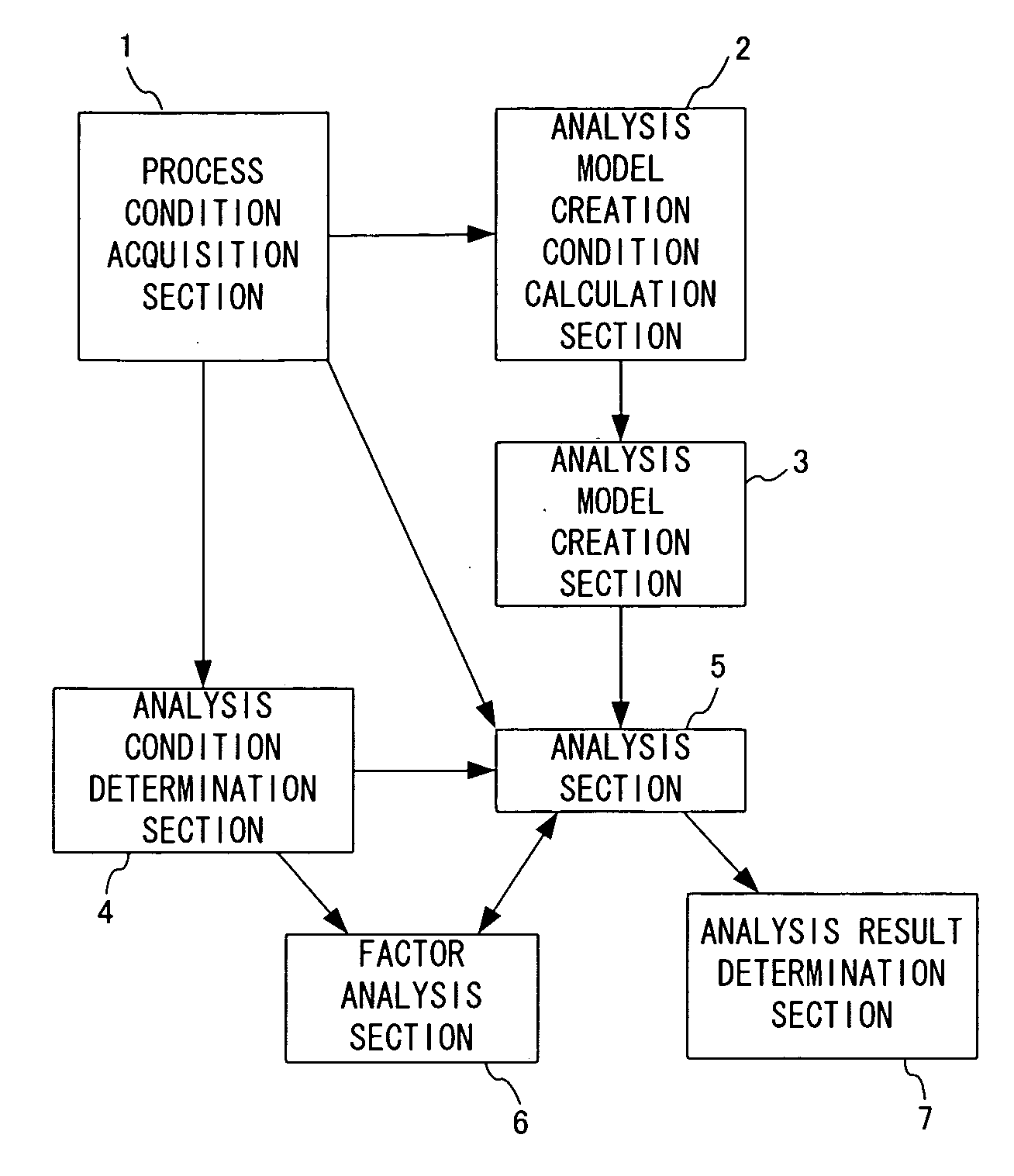
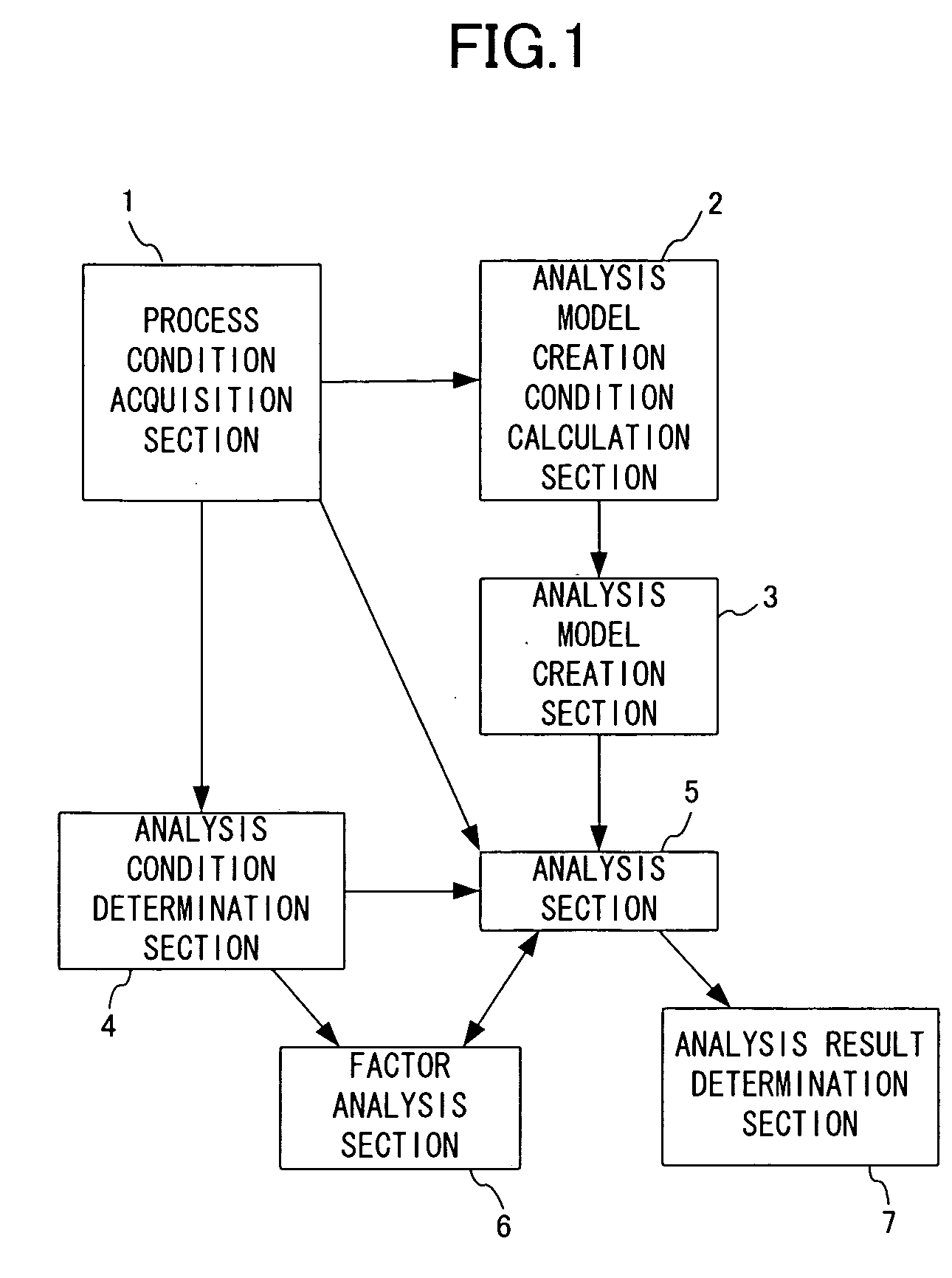
[0035]FIG. 1 is a block diagram showing an example of the laser bending process estimation apparatus according to the present invention. The laser bending process estimation apparatus includes a process condition acquisition section 1, an analysis model creation condition calculation section 2, an analysis model creation section 3, an analysis condition determination section 4, an analysis section 5, a factor analysis section 6, and an analysis result determination section 7. The analysis model creation section 3 is realized by, for example, a mesh modeler. The analysis section 5 is realized by, for example, a general-purpose f...


PUM

PropertyMeasurementUnit
temperatureaaaaaaaaaa
bending process estimationaaaaaaaaaa
heat energyaaaaaaaaaa

Abstract

The present invention has been made to provide a laser bending process estimation apparatus, a laser bending process estimation program, and a laser bending process estimation method capable of estimating a result of a laser bending process without an actual workpiece.
A laser bending process estimation apparatus that estimates a result of a bending process performed using a laser beam comprises: a process condition acquisition section 1 that acquires a process condition of the bending process; an analysis model creation section 3 that creates an analysis model based on the process condition acquired by the process condition acquisition section 1; and an analysis section 5 that performs heat transfer analysis and heat stress analysis based on the analysis model created by the analysis model creation section 3 to calculate an analysis result of the bending process.

Description

BACKGROUND OF THE INVENTION [0001] 1. Field of the Invention [0002] The present invention relates to a bending process estimation apparatus, a bending process estimation program, and a bending process estimation method that estimate the result of a bending process. [0003] 2. Description of the Related Art [0004] A bending process for plate forming using a laser beam has been used in a situation where high processing accuracy is required. This is a technique that irradiates a plate with a laser beam to cause thermal gradient in the thickness direction of the plate to thereby bend the plate. For example, this laser bending process for plate has been used in the case where deviations in the pitch and roll angles are corrected in a suspension process for HDD (Hard Disk Drive). [0005] Conventionally, at the time of launching a manufacturing process for a new model, a large number of samples are used, a laser beam is irradiated onto the samples (workpiece materials) under various process ...

Claims


Application Information

Patent Timeline
Patent Type & Authority Applications(United States)
IPC IPC(8): G06F19/00B21D11/20B23K26/00
CPCG06F2217/42G06F17/5009G06F30/20G06F2113/24
Inventor TATENO, TADASHI
Owner FUJITSU LTD
Why Eureka
Try Eureka