
Remote NMR/MRI detection of laser polarized gases

a laser polarized gas and remote detection technology, applied in the field of nuclear magnetic resonance spectroscopy, can solve the problems of inability to detect laser polarized gases, device limitations, and insensitivity of nmr, and achieve the effects of increasing the signal to noise ratio, maximizing the filling factor, and high spin density

Inactive Publication Date: 2006-06-13
RGT UNIV OF CALIFORNIA
View PDF33 Cites 27 Cited by
  • Summary
  • Abstract
  • Description
  • Claims
  • Application Information

AI Technical Summary

Benefits of technology

[0032]According to another aspect of the invention, the method of the invention may also include concentrating the encoded signal carriers in the detection analysis vessel or chamber by physical compression or thermal condensation, for example. Concentration of the encoded signal carriers increases the signal to noise ratios and provides a higher spin density.
[0043]Another object of the invention is to provide an apparatus and method that can provide remote NMR with detection magnets with poor field homogeneity.

Problems solved by technology

However, NMR is a relatively insensitive detection method compared to others since the NMR signal depends on the population difference between two spin states.
However, SQUID devices exhibit instability in the presence of the pulsed magnetic fields that are necessary to prepare (encode) nuclear magnetization for detection.
Consequently, these devices may be limited in their utility because of this instability.

Method used


Image

  • Remote NMR/MRI detection of laser polarized gases
  • Remote NMR/MRI detection of laser polarized gases
  • Remote NMR/MRI detection of laser polarized gases

Examples


example 1

[0095]A preliminary test of the concept of remote detection used an apparatus in which both an encoding coil and detection coil were controlled within the same NMR spectrometer with the same magnetic field and had a minimal travel distance between the encoding and detection coils. The high field encoding probe that was used contains two coils that are separated by 2 cm, center to center, and by a copper sheet, which serves as an rf shield. The encoding and detection coils were each controlled by a separate x-channel of a Varian Infinity Plus spectrometer tuned to 83.25 MHz.

[0096]Hyperpolarized 129Xe, polarized to 1-5%, was produced using a commercial polarizer from MITI. After the polarized 129Xe gas was produced, the flow was directed through the encoding and detecting coils sequentially and was later lost into the laboratory atmosphere or was alternatively returned to the polarizer. Gas flow rate was controlled using a pressure differential through a silver coated needle valve and...

example 2

[0102]Using an apparatus shown generally in FIG. 3, a low field encoding and high field detecting procedure was performed. In this procedure, two dimensional images were obtained from a sample and Xe gas that was encoded at 0.008 T and detected at 4 T. The experimental apparatus and pulse sequence were identical to that in Example 1 with the exception that frequency encoding gradients were added between the two encoding 90° pulses. The travel time was set to 10 seconds corresponding to a flow rate of ˜0.6 ml / s.

[0103]In order for a remote image to be properly reconstructed in the detection coil, preferably all of the encoded gas will be detected in the detection coil. The processes of diffusion and flow allow the encoded sample to mix with un-encoded gas and to spatially spread out along the length of tubing. The total distance traveled is approximately 5 m, but the movement of the encoded sample is better measured in terms of travel time.

[0104]The traveling time Tt is preferably det...


PUM


Abstract

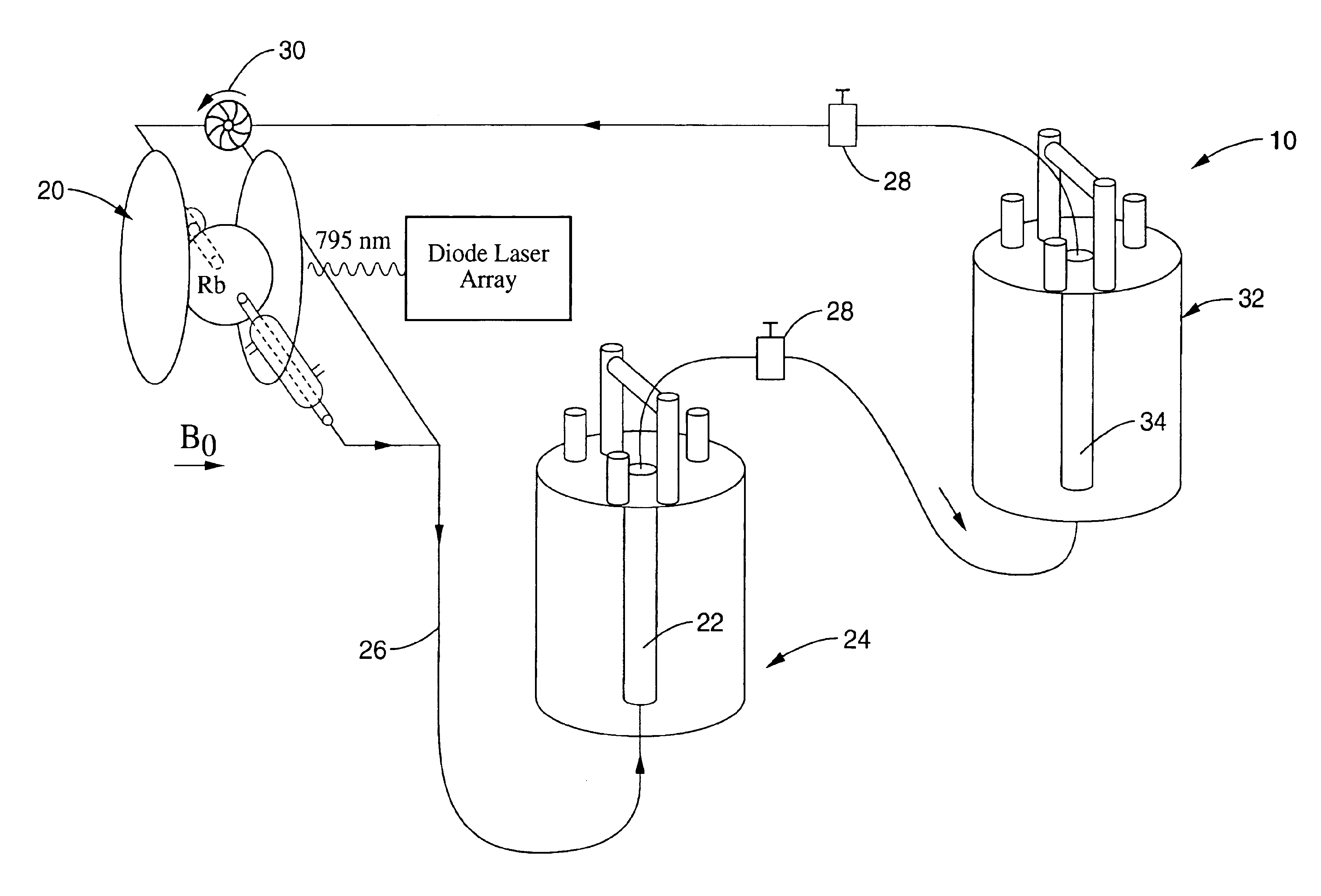
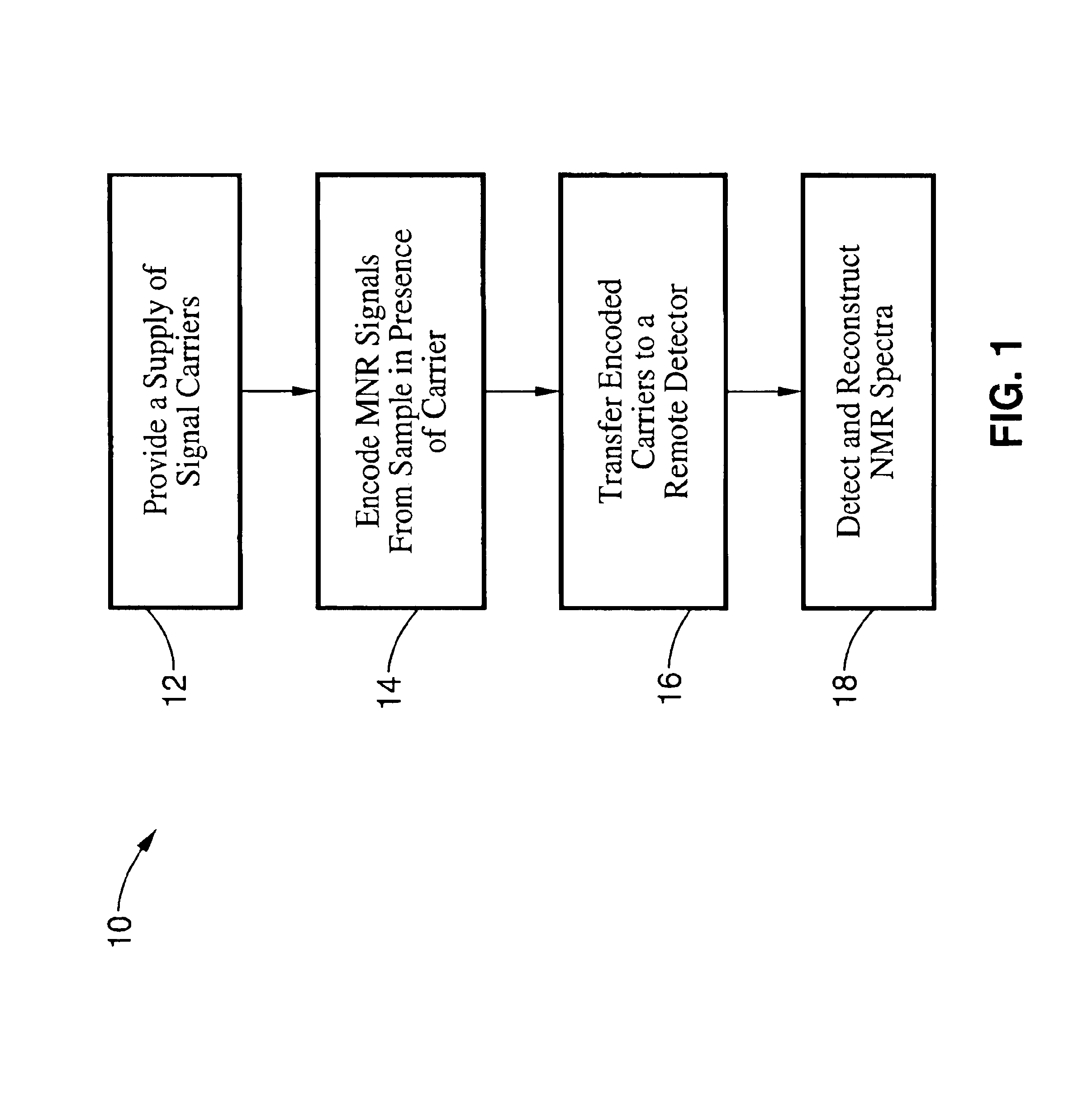
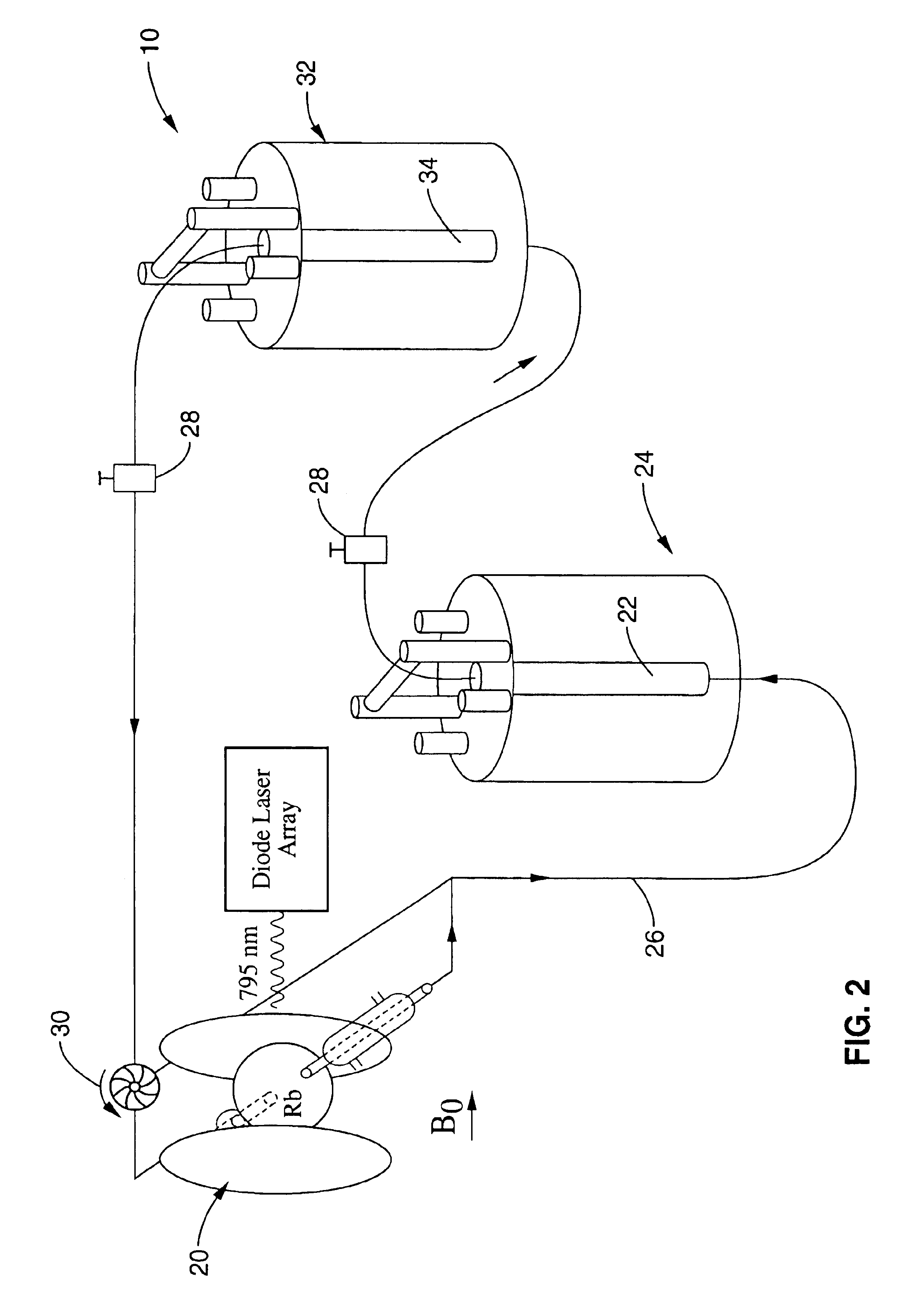
An apparatus and method for remote NMR / MRI spectroscopy having an encoding coil with a sample chamber, a supply of signal carriers, preferably hyperpolarized xenon and a detector allowing the spatial and temporal separation of signal preparation and signal detection steps. This separation allows the physical conditions and methods of the encoding and detection steps to be optimized independently. The encoding of the carrier molecules may take place in a high or a low magnetic field and conventional NMR pulse sequences can be split between encoding and detection steps. In one embodiment, the detector is a high magnetic field NMR apparatus. In another embodiment, the detector is a superconducting quantum interference device. A further embodiment uses optical detection of Rb—Xe spin exchange. Another embodiment uses an optical magnetometer using non-linear Faraday rotation. Concentration of the signal carriers in the detector can greatly improve the signal to noise ratio.

Description

CROSS-REFERENCE TO RELATED APPLICATIONS[0001]This application is a continuation-in-part of U.S. application Ser. No. 09 / 903,279 filed on Jul. 11, 2001, now U.S. Pat. No. 6,652,833 which in turn claims priority from U.S. provisional application Ser. No. 60 / 218,549 filed on Jul. 13, 2000.[0002]This application also claims priority from U.S. provisional application Ser. No. 60 / 399,041 filed on Jul. 25, 2002, from U.S. provisional application Ser. No. 60 / 335,173 filed on Oct. 31, 2001, from U.S. provisional application Ser. No. 60 / 409,410 filed on Sep. 9, 2002, and from U.S. provisional application Ser. No. 60 / 335,240 filed on Oct. 31, 2001.[0003]This application is related to and incorporates by reference PCT International Publication No. WO 01 / 05803 A1 published on Jan. 24, 2002.STATEMENT REGARDING FEDERALLY SPONSORED RESEARCH OR DEVELOPMENT[0004]This invention was made with Government support under Contract No. DE-AC0376F00098, awarded by the United States Department of Energy. The G...

Claims


Application Information

Patent Timeline
Patent Type & Authority Patents(United States)
IPC IPC(8): G01V3/00A61K49/18G01R33/28G01R33/46
CPCA61K49/1815G01R33/46G01R33/282G01R33/5601
Inventor PINES, ALEXANDERSAXENA, SUNILMOULE, ADAMSPENCE, MEGANSEELEY, JULIETTE A.PIERCE, KIMBERLY L.HAN, SONG-IGRANWEHR, JOSEF
Owner RGT UNIV OF CALIFORNIA
Learn More