Velocity detection, position detection and navigation system
- Summary
- Abstract
- Description
- Claims
- Application Information
AI Technical Summary
Benefits of technology
Problems solved by technology
Method used
Image
Examples
first embodiment
(1) First Embodiment
(1-1) Configuration of Navigation System
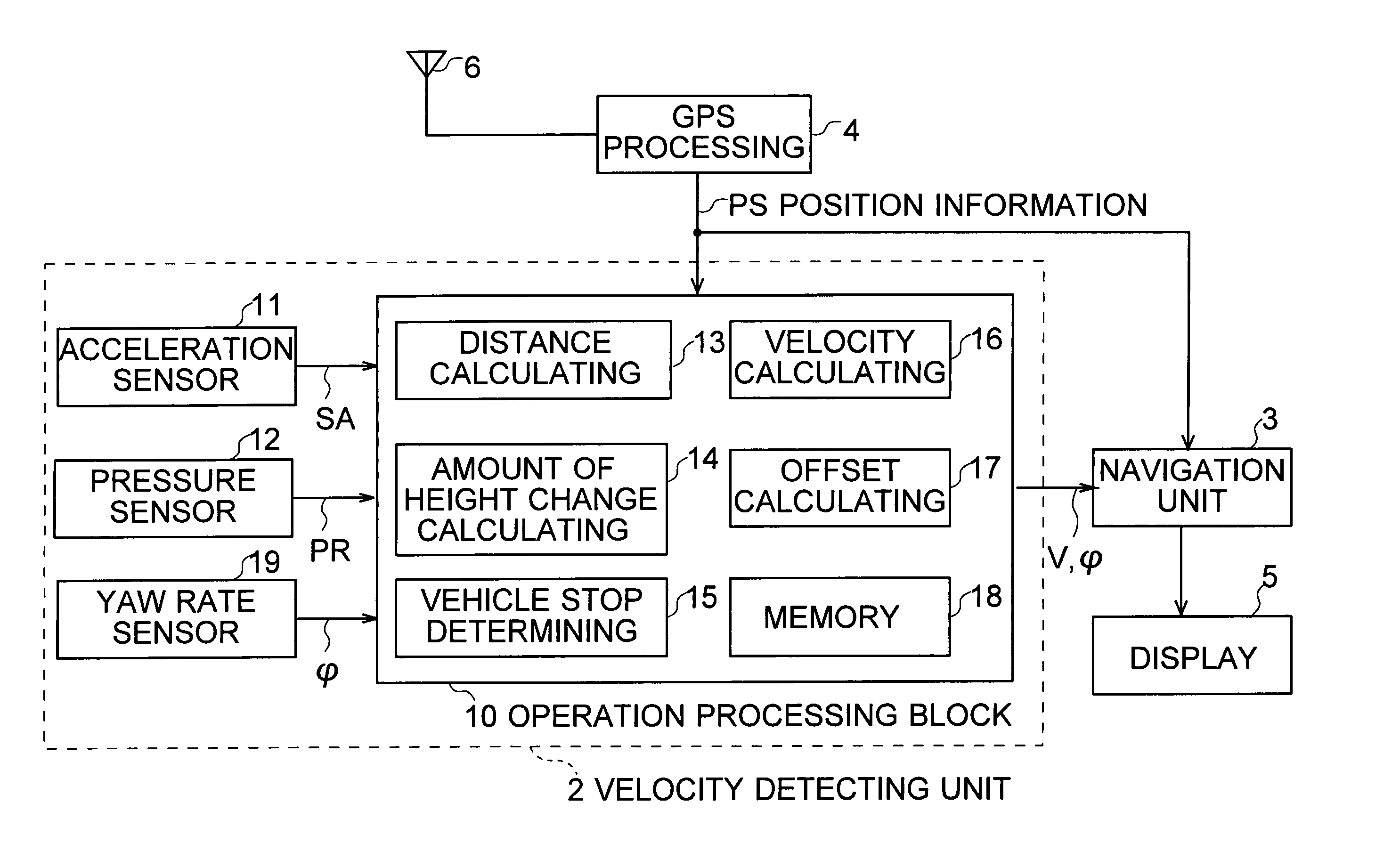
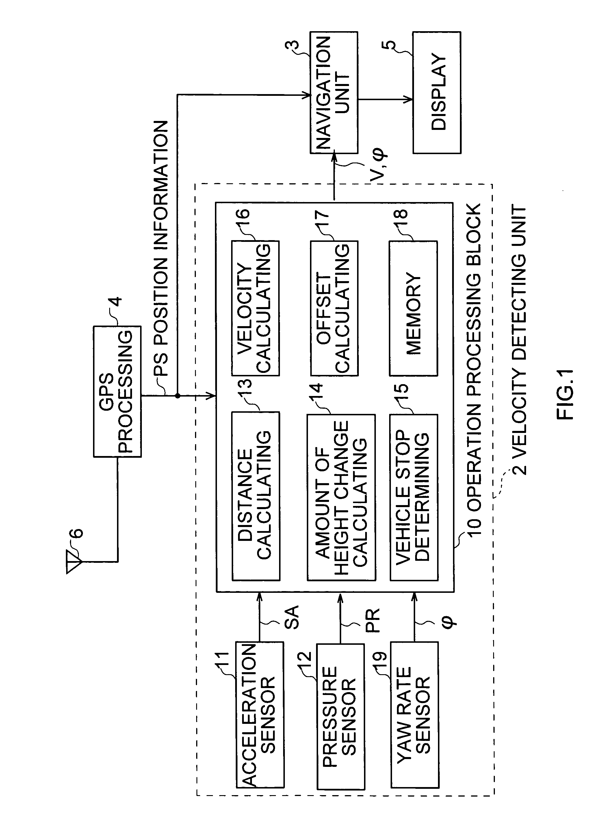
[0033] Referring to FIG. 1, a navigation system 1 is installed in a vehicle 100 (FIG. 2A) serving as a mobile body. The present position of the vehicle 100 is calculated by a Global Positioning System (GPS) processing section 4, based on a GPS signal received from a GPS satellite, display screen data is generated by superimposing a mark indicating the present position of the vehicle 100 or the like on predetermined map data by a navigation unit 3, and this is transmitted to a display section 5 and a display screen is displayed. Thereby, the user can see the position of the vehicle 100 on a map.
[0034] The GPS processing section 4 receives GPS signals from a plurality of GPS satellites (not shown) via a GPS antenna 6, generates position information PS by performing predetermined position calculating processing based on the GPS signals, and supplies this to an operation processing block 10 in a velocity detecting unit 2 and...
second embodiment
(2) Second Embodiment
(2-1) Configuration of Navigation System
[0132] As shown in FIG. 9 in that the same reference numerals are added to the corresponding parts in FIG. 1, a navigation system 20 in a second embodiment has a similar configuration to the navigation system 1 (FIG. 1) other than that a velocity detecting unit 21 is provided instead of the velocity detecting unit 2.
[0133] The velocity detecting unit 21 has an operation processing block 22 instead of the operation processing block 10 in the velocity detecting unit 2 (FIG. 1). In the operation processing block 22, in addition to the configuration of the operation processing block 10, an angular velocity correcting section 23 for performing the correcting processing of an angular velocity φ supplied from the yaw rate sensor 19 is provided.
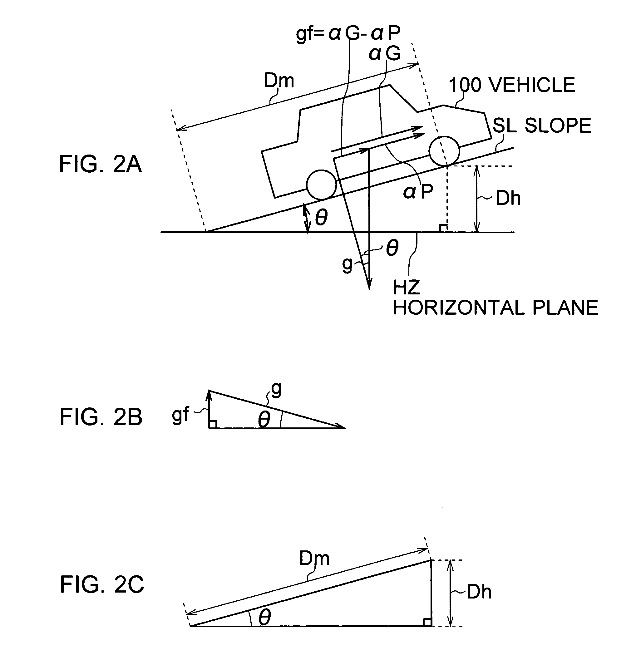
[0134] As shown in FIG. 10A that corresponds to FIG. 2A, it is assumed that the vehicle 100 is running on a slope SL that has a slope angle θ to a horizontal plane HZ, in a forward dire...
PUM
 Abstract
Description
Claims
Application Information
 - R&D
- Intellectual Property
- Life Sciences
- Materials
- Tech Scout
- Unparalleled Data Quality
- Higher Quality Content
- 60% Fewer Hallucinations
Browse by: Latest US Patents, China's latest patents, Technical Efficacy Thesaurus, Application Domain, Technology Topic, Popular Technical Reports.
© 2025 PatSnap. All rights reserved.Legal|Privacy policy|Modern Slavery Act Transparency Statement|Sitemap|About US| Contact US: help@patsnap.com


