Method of estimating magnetic pole position in synchronous motor

a synchronous motor and magnetic pole technology, applied in the direction of electronic commutators, motor/generator/converter stoppers, dynamo-electric converter control, etc., can solve the problems of difficult downsizing a motor with a position detector, the amount of calculation required for estimation is enormous, and the motor cannot be stably operated, etc., to achieve the effect of reducing the amount of calculation required for estimation, enhancing the accuracy of estimation, and not substantially lowering the accuracy ratio ratio ratio ratio ratio ratio ratio ratio ratio ratio ratio ratio ratio ratio ratio ratio ratio ratio ratio ratio ratio ratio ratio ratio ratio ratio ratio ratio ratio ratio ratio ratio ratio ratio ratio ratio ratio ratio ratio ratio ratio ratio ratio ratio ratio ratio ratio ratio ratio ratio ratio ratio ratio ratio ratio ratio ratio ratio ratio ratio ratio ratio ratio ratio ratio ratio ratio ratio ratio ratio ratio ratio ratio ratio ratio ratio ratio ratio ratio ratio ratio ratio ratio ratio ratio ratio ratio ratio ratio ratio ratio ratio ratio ratio ratio ratio ratio ratio ratio ratio ratio ratio ratio ratio

Active Publication Date: 2007-03-29
DENSO CORP
View PDF3 Cites 40 Cited by
  • Summary
  • Abstract
  • Description
  • Claims
  • Application Information

AI Technical Summary

Benefits of technology

[0011] An object of the present invention is to provide, with due consideration to the drawbacks of the conventional estimation of a magnetic pole position, a method wherein a magnetic pole position of a rotor in a synchronous motor is correctly estimated while reducing an amount of calculation required for the estimation without substantially lowering precision in the estimation.
[0013] Although a wave height of the alternating current is slightly changed with time, this wave height is approximated to or replaced with a wave height substantially not depending on time. In this case, differential terms in the calculation of the induced voltage from the applied alternating current voltage and the detected alternating current can be removed. Therefore, an amount of calculation required for the estimation can be considerably reduced, and precision in the estimation is not substantially lowered. As compared with an induced voltage model constituted on the dq rotational coordinates system, precision in the estimation can be heightened.

Problems solved by technology

However, it is difficult to downsize a motor with a position detector, and it is required to connect the detector with a controller for controlling the motor through connection lines.
As a result, when the motor is controlled according to the estimated position, the motor cannot stably be operated.
However, because the model includes a differential term to calculate an induced voltage in detail, an amount of calculation required for the estimation is enormously increased.

Method used


Image

  • Method of estimating magnetic pole position in synchronous motor
  • Method of estimating magnetic pole position in synchronous motor
  • Method of estimating magnetic pole position in synchronous motor

Examples


embodiment 1

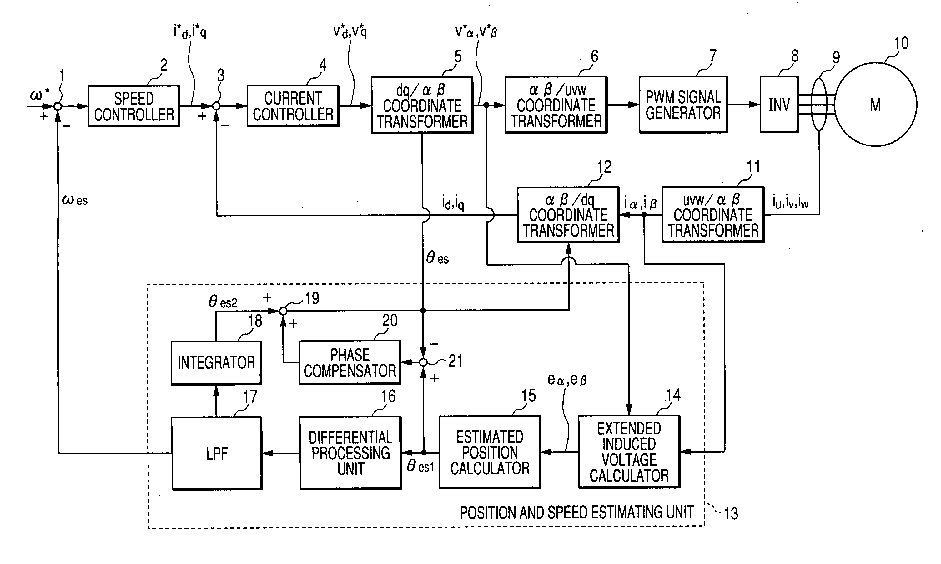
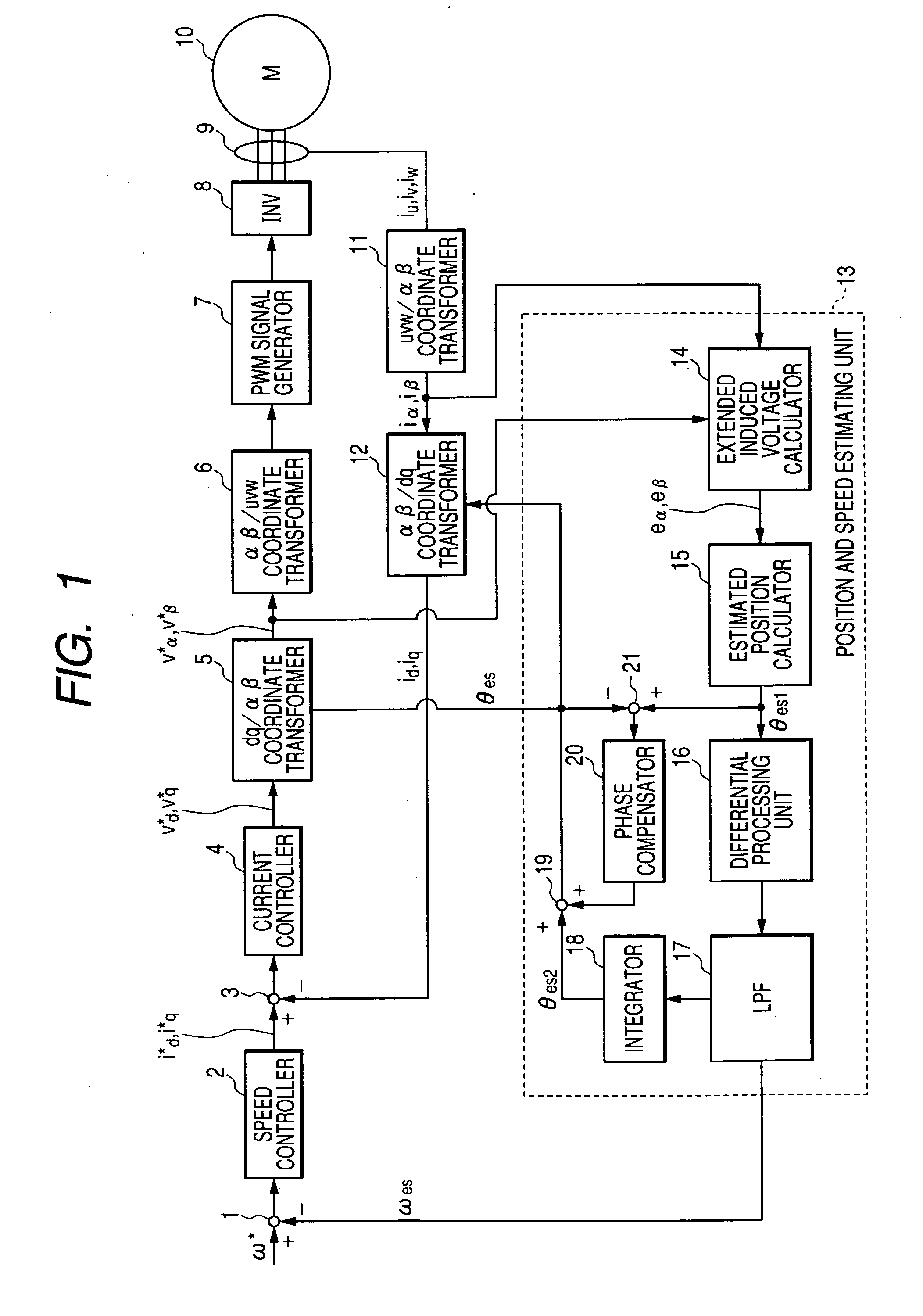
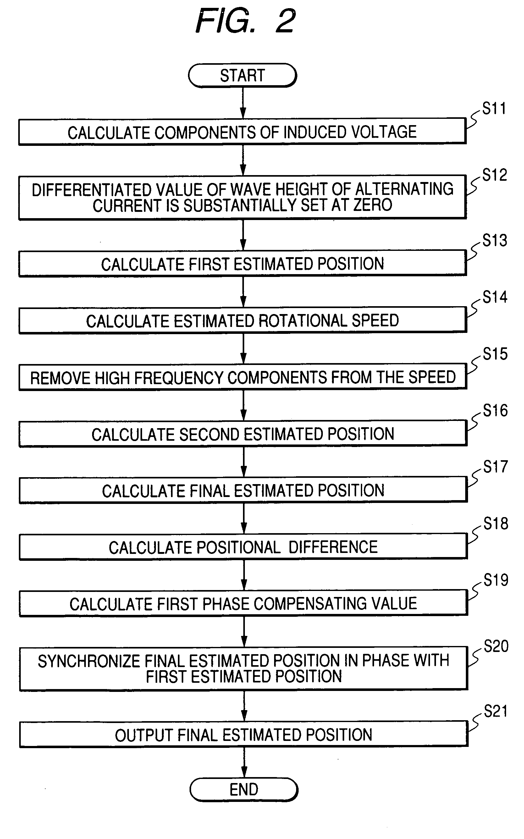
[0034]FIG. 1 is a block diagram of a control unit for a synchronous motor wherein a method according to a first embodiment of the present invention is performed. FIG. 2 is a flow chart showing the procedure of a method of estimating a magnetic pole position according to the first embodiment.

[0035] A synchronous motor 10 shown in FIG. 1 has windings of a stator and a rotor (not shown) made of permanent magnets. When a three-phase alternating current voltage is applied to the windings, a three-phase alternating current composed of phase currents of U, V and W phases flows through the windings so as to generate a changeable magnetic field due to electromagnetic induction, and the rotor having the permanent magnets is rotated on its rotation axis in response to the magnetic field. The rotational force is outputted through a transmitter such as a pulley and a belt. A phase of the current is controlled in a control unit shown in FIG. 1 to stably rotate the rotor at a desired rotational s...

embodiment 2

[0065]FIG. 4 is a flow chart showing the procedure of a method of estimating a magnetic pole position according to a second embodiment of the present invention. FIG. 5 is a block diagram of another estimating unit 24 wherein the method shown in FIG. 4 is performed.

[0066] As shown in FIG. 4 and FIG. 5, an estimating unit 24 has a phase compensating adder 22 arranged between the filter 17 and integrator 18, in place of the adder 19. The adder 22 adds a second phase compensating value outputted from the compensator 20 to the speed ωes outputted from the filter 17 to obtain a phase compensated speed ωes (step S41). The integrator 18 integrates this speed ωes with respect to time to obtain a final estimated magnetic pole position θes (step S42). The calculator 21 calculates a positional difference Δθ es (=θes1−θes) between the estimated positions θes1 and θes (step S43). The compensator 20 multiplies the difference Δθes by a second PI gain set at a value of Kp2+Ki2 / s to obtain the secon...

embodiment 3

[0071] In the first embodiment, to remove high frequency components (i.e., noises) superimposed on extended induced voltage components eα and eβ, the position θes1 expressed by an alternating current component is converted into the speed ωes expressed by a direct current component. In contrast, in the third embodiment, the voltage components eα and eβ expressed by alternating current components are directly converted into extended induced voltage components ed and eq expressed by direct current components to remove noises from the voltage components ed and eq.

[0072]FIG. 7A shows a wave shape of an extended induced voltage in the αβ coordinates system, FIG. 7B shows a wave shape of an extended induced voltage in the dq coordinates system, FIG. 7C shows a wave shape of a filtered extended induced voltage in the dq coordinates system, and FIG. 7D shows a wave shape of a filtered extended induced voltage in the αβ coordinates system. FIG. 8 is a flow chart showing the procedure of a me...


PUM


Abstract

In a method of estimating a magnetic pole position in a synchronous motor, an alternating current voltage having α- and β-axes components in an αβ coordinates system representing a two-phase alternating current coordinates system is applied to the motor, and α- and β-axes components of an alternating current are detected from the motor. A wave height of the alternating current changing with time is approximated to a wave height not depending on time, so that a differentiated value of the wave height with respect to time is substantially set at zero. An induced voltage of the motor is calculated from the components of the alternating current voltage and the components of the alternating current. The magnetic pole position is estimated from the induced voltage.

Description

CROSS-REFERENCE TO RELATED APPLICATION [0001] This application is based upon and claims the benefit of priority of the prior Japanese Patent Application 2005-280410 filed on Sep. 27, 2005 so that the contents of which are incorporated herein by reference. BACKGROUND OF THE INVENTION [0002] 1. Field of the Invention [0003] The present invention relates to a method of estimating a position (e.g., magnetic pole position) of a rotor in a synchronous motor wherein permanent magnets are used for the rotor. [0004] 2. Description of Related Art [0005] In a synchronous motor such as a surface permanent magnetic synchronous motor (SPMSM) or an internal permanent magnetic synchronous motor (IPMSM), permanent magnets are used for a rotor, and S and N magnetic poles formed by the permanent magnets are alternately disposed around a shaft of the rotor. During the operation of this motor, an alternating current voltage is applied to windings of a stator, and an alternating current generated from th...

Claims


Application Information

Patent Timeline
Patent Type & Authority Applications(United States)
IPC IPC(8): H02P1/46H02P6/18H02P6/06H02P6/08H02P6/182H02P6/28H02P29/00
CPCH02P6/182H02P2207/05H02P21/146H02P21/18
Inventor IMURA, AKIHIROAOKI, YASUAKI
Owner DENSO CORP
Why Eureka
Try Eureka