
Eureka
For R&D, Eureka makes reading and utilizing patents & technical documents easy.
Eureka AIR
Designed for self-driven R&D workflows. Generate viable solutions, solve complex R&D challenges, empower your innovation with AI.

Eureka Materials
Designed for material experts only. Revolutionize your material R&D, from search, analyze, to developing new materials.

TechResearch
Generate reliable direction feasibility study reports for your R&D in just a few steps.

TechSeek
Discover and master advanced knowledge NOW. Basics, ideas, possibilities, all at once.

TechMind
As an expert in R&D Theories, TechMind can generates customized viable solutions instantly.

TechRisk
Analyze your overall solution with one click, know your potential R&D risks in advance.

TechMonitor
Get weekly tech updates, stay abreast of the latest tech innovations and key insights.
Controller for DC-DC converter and method for controlling DC-DC converter
- Summary
- Abstract
- Description
- Claims
- Application Information
AI Technical Summary
Benefits of technology
Problems solved by technology
Method used
Image

Examples
first embodiment
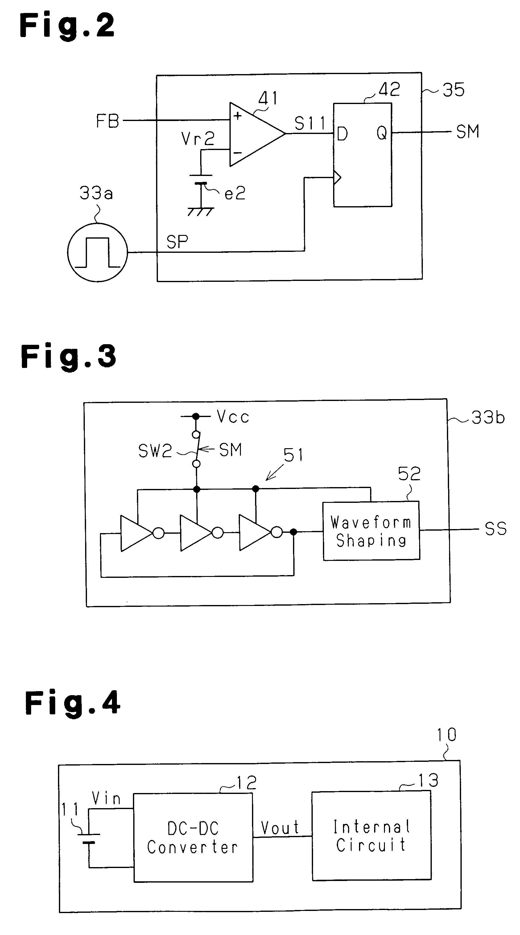
[0028] A DC-DC converter 12 according to the present invention will now be described with reference to the drawings.
[0029]FIG. 4 is a schematic block diagram of an electronic device 10 including the DC-DC converter 12. The electronic device 10 is portable and is powered by a built-in battery 11. The battery 11 is connected to the DC-DC converter 12, which functions as a power supply circuit. The DC-DC converter 12 is connected to an internal circuit 13 such as a CPU. The DC-DC converter 12 converts input voltage Vin supplied from the battery 11 to output voltage Vout, which is a constant voltage for operating the internal circuit 13 and supplies the output voltage Vout to the internal circuit 13.
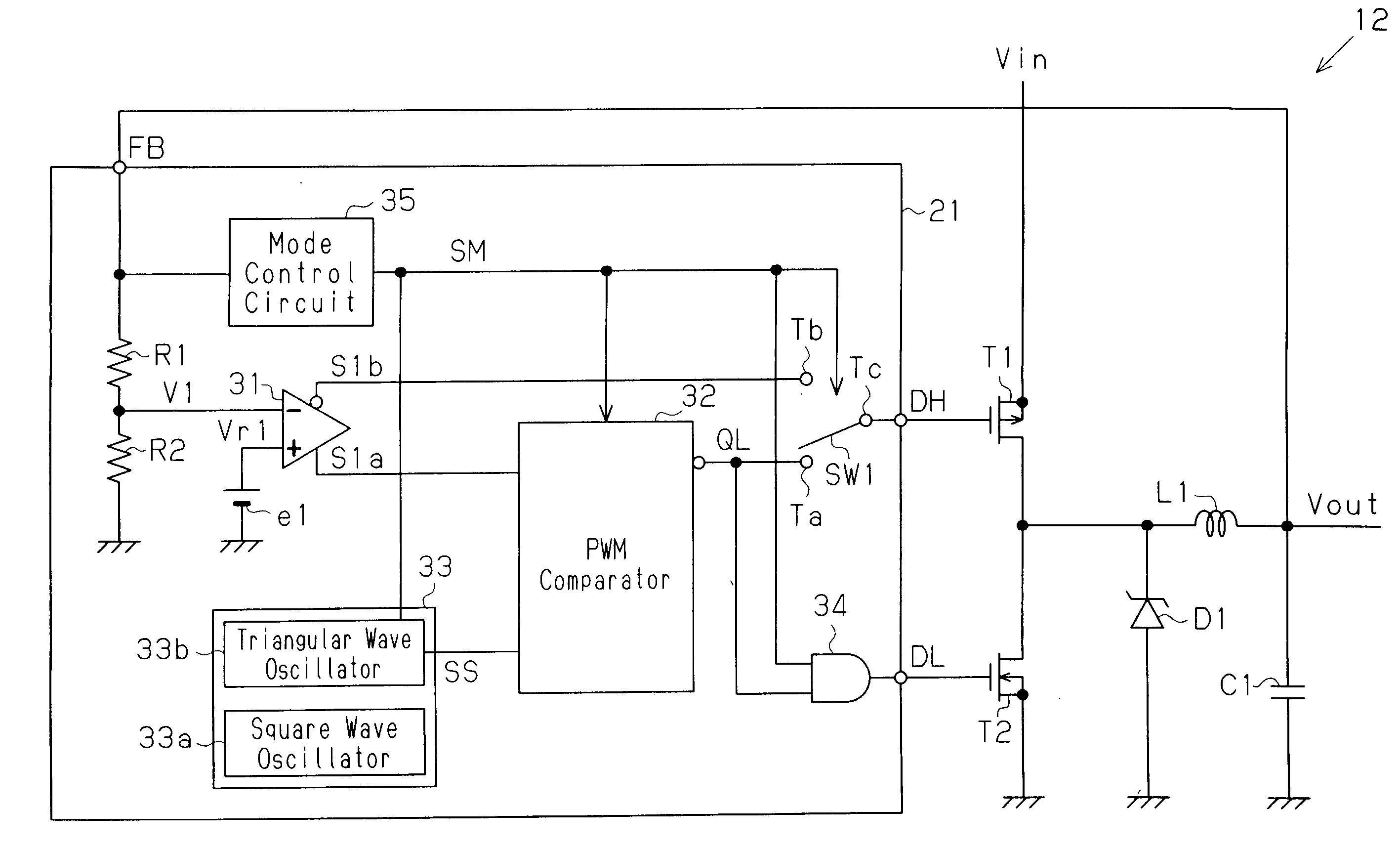
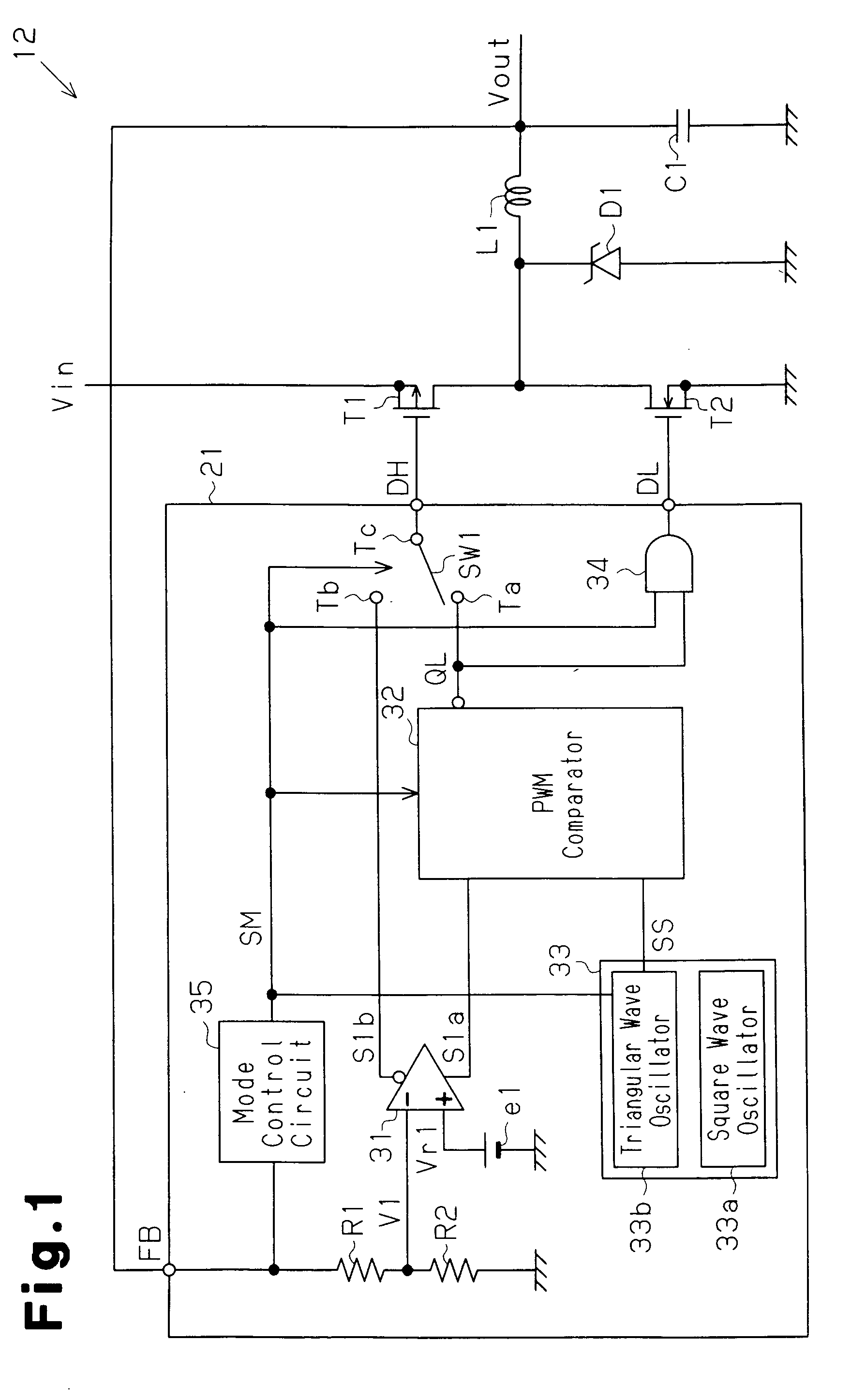
[0030] The configuration of the DC-DC converter 12 will now be described.
[0031] The DC-DC converter 12 shown in FIG. 1 is a voltage controlling mode DC-DC converter and includes a controller 21, an output transistor T1 serving as a main switching transistor, an output transistor T2 serving...
second embodiment
[0069] A DC-DC converter 12a according to the present invention will now be described with reference to the drawings.
[0070]FIG. 5 is a schematic block diagram of the DC-DC converter 12a in the second embodiment of the present invention. The DC-DC converter 12a is a voltage controlling mode DC-DC converter and similar to that of the first embodiment. The DC-DC converter 12a replaces the DC-DC converter 12 of the first embodiment. More specifically, the DC-DC converter 12a converts the input voltage Vin input from the battery 11 shown in FIG. 4 into the output voltage Vout, which is a constant voltage for operating the internal circuit 13, and supplies the output voltage Vout to the internal circuit 13.
[0071] The DC-DC converter 12a includes a controller 21a, an output transistor T1 serving as a main switching transistor, an output transistor T2 serving as a synchronous rectifying transistor, a choke coil L1, a diode D1, and a smoothing capacitor C1.
[0072] The controller 21a include...
third embodiment
[0090] A DC-DC converter 70 according to the present invention will now be described with reference to the drawings.
[0091]FIG. 7 is a schematic block diagram of a DC-DC converter 70 according to a third embodiment of the present invention. The DC-DC converter 70, which is a current controlling mode DC-DC converter, includes a controller 71, the output transistors T1 and T2, the choke coil L1, the smoothing capacitor C1, the diode D1, and a current detection resistor Rs. The output voltage Vout is output via the current detection resistor Rs.
[0092] In the controller 71, the feedback signal CS having the voltage of the first terminal of the current detection resistor Rs is provided to a non-inverting input terminal of a voltage amplifier 72. The feedback signal FB having the voltage of the second terminal of the current detection resistor Rs is provided to an inverting input terminal of the voltage amplifier 72. The voltage amplifier 72 amplifies the voltage generated between the two...
PUM
 Abstract
Description
Claims
Application Information
 - R&D Engineer
- R&D Manager
- IP Professional
- Industry Leading Data Capabilities
- Powerful AI technology
- Patent DNA Extraction
Browse by: Latest US Patents, China's latest patents, Technical Efficacy Thesaurus, Application Domain, Technology Topic, Popular Technical Reports.
© 2024 PatSnap. All rights reserved.Legal|Privacy policy|Modern Slavery Act Transparency Statement|Sitemap|About US| Contact US: help@patsnap.com