Method and apparatus for preamble synchronization in wireless radio frequency identification (RFID) systems

a wireless radio frequency identification and preamble synchronization technology, applied in electrical equipment, digital transmission, time-division multiplex, etc., can solve the problems of reducing the probability of correctly decoding received data, multipath propagation, and severe interference of rfid communication channels, and achieve simple implementation and high performance.

Inactive Publication Date: 2007-03-29
SYMBOL TECH INC
View PDF11 Cites 32 Cited by
  • Summary
  • Abstract
  • Description
  • Claims
  • Application Information

AI Technical Summary

Benefits of technology

[0012] Efficient signal processing procedures are described for detecting the preamble portion of signal packets, such as in RFID systems, which provide for high performance in relatively simple implementations.
[0013] In aspects of the present invention, methods and systems for detecting a preamble portion of a signal are provided. A preamble is typically an initial portion of a data packet, which is followed by the actual data of the data packet. Detecting the preamble portion of the data packet enables the recovery of data from the remainder of the data packet.

Problems solved by technology

A RFID communication channel is usually plagued with severe interference, multipath propagation, and fast fading, especially when a tag or / and a reader are moving.
Therefore, any failure in correctly detecting the preamble decreases the probability of correctly decoding the received data, including causing increased BLER.

Method used


Image

  • Method and apparatus for preamble synchronization in wireless radio frequency identification (RFID) systems
  • Method and apparatus for preamble synchronization in wireless radio frequency identification (RFID) systems
  • Method and apparatus for preamble synchronization in wireless radio frequency identification (RFID) systems

Examples


example rfid system embodiment

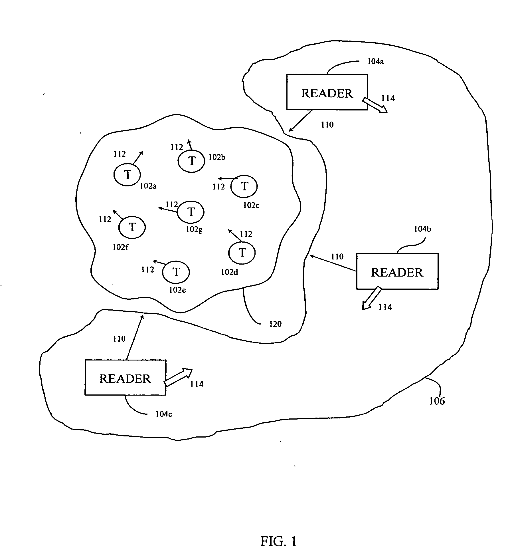
[0046] Before describing embodiments of the present invention in detail, it is helpful to describe an example RFID communications environment in which the invention may be implemented. FIG. 1 illustrates an environment 100 where RFID tag readers 104 communicate with an exemplary population 120 of RFID tags 102. As shown in FIG. 1, the population 120 of tags includes seven tags 102a-102g. According to embodiments of the present invention, a population 120 may include any number of tags 102.

[0047] Environment 100 includes either a single reader 104 or a plurality of readers 104, such as readers 104a-104c. In an embodiment, a reader 104 may be requested by an external application to address the population of tags 120. Alternatively, reader 104 may have internal logic that initiates communication, or may have a trigger mechanism that an operator of reader 104a uses to initiate communication.

[0048] As shown in FIG. 1, readers 104 transmit an interrogation signal 110 having a carrier fr...

reader embodiment

Example Conventional RFID Reader Embodiment

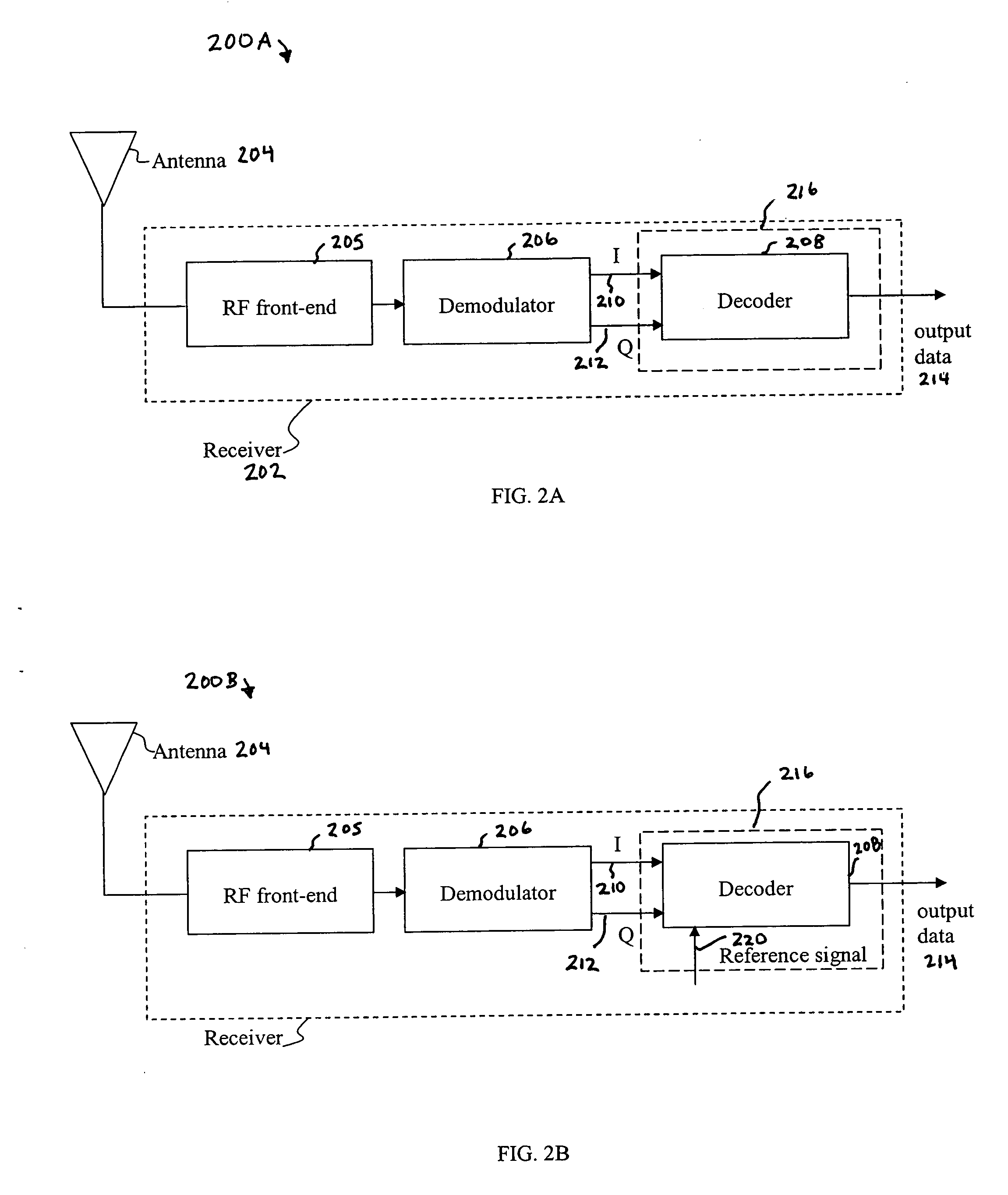
[0052]FIG. 2A shows an example block diagram of the receiver portion of a conventional RFID reader 200A. Reader 200A typically includes one or more antennas 204, one or more receivers 202, one or more transmitters, one or more memory units, and one or more processors (transmitters, memory units, and processors are not shown in FIG. 2A). As shown in the example of FIG. 2A, receiver 202 includes a RF front-end 205, a demodulator 206, and a decoder 208. These components of reader 200A may include software, hardware, and / or firmware, or any combination thereof, for performing their functions, which are described in further detail in subsequent sections herein.

[0053] Reader 200A has at least one antenna 204 for communicating with tags 102 and / or other readers 104. In an example FCC environment, interrogator transmission and tag responses are spectrally separated. A tag response signal includes data modulated according to an amplitude shift keyi...

example system embodiments

[0084] In embodiments, preamble detection systems can be configured to operate on one or more components of an input signal, such as I-phase and Q-phase components of an input signal. Thus, in an I / Q implementation, the I-phase and Q-phase components can both be processed in separate channels to detect the preamble of the input signal, and the results from one or both of the I-phase and Q-phase channels can be utilized as desired.

[0085]FIG. 7 shows an example preamble detection system 700 that can be implemented in the base-band portion of a receiver used in a wireless communication system, such as base-band portion 216. As shown in FIG. 7, system 700 includes an I-channel portion 702a and a Q-channel portion 702b. I-channel portion 702a includes a counter 704a, a matched filter 706a, a preamble detection flag register 708a, and a signal level detector 710a. Q-channel portion 702b includes a counter 704b, a matched filter 706b, a preamble detection flag register 708b, and a signal ...


PUM


Abstract

The present invention provides methods and apparatuses for detection of a preamble portion of a data packet. A plurality of samples are received in an input signal. Samples that occur between consecutive sign changes in the received plurality of samples are counted. The counting of samples is performed a number of times to produce a sequence of counts of samples between consecutive sign changes in the received plurality of samples. Matched filtering of the sequence of counts of samples is performed to determine whether a preamble is detected. Bit rate and timing are initialized for data decoding based on parameters of the sequence of sample counts of a detected preamble.

Description

BACKGROUND OF THE INVENTION [0001] 1. Field of the Invention [0002] The present invention relates to wireless communications, and more particularly, to radio frequency identification (RFID) communication systems, including readers that demodulate and decode signals received from RFID tags. [0003] 2. Background Art [0004] Radio frequency identification (RFID) tags are electronic devices that may be affixed to items whose presence is to be detected and / or monitored. The presence of an RFID tag, and therefore the presence of the item to which the tag is affixed, may be checked and monitored wirelessly by devices known as “readers.” Readers typically have one or more antennas transmitting radio frequency signals to which tags respond. Since the reader “interrogates” RFID tags, and receives signals back from the tags in response to the interrogation, the reader is sometimes termed as “reader interrogator” or simply “interrogator”. [0005] With the maturation of RFID technology, efficient ...

Claims


Application Information

Patent Timeline
Patent Type & Authority Applications(United States)
IPC IPC(8): H04J3/06
CPCH04L7/042
Inventor OKUNEV, YURIMAIZENBERG, VALERY
Owner SYMBOL TECH INC
Why Eureka
Try Eureka