Stent delivery system

a technology of stent and stent body, which is applied in the field of stent delivery system, can solve the problems of limiting the degree to which the system can be miniaturized, limiting the degree of flexibility of all known sheath/pusher systems, and requiring large profiles. achieve the effect of maximizing the often conflicting objectives of flexibility, improving pushability, trackability and implant deployment characteristics

Inactive Publication Date: 2007-03-29
BIOSENSORS INT GROUP
View PDF99 Cites 107 Cited by
  • Summary
  • Abstract
  • Description
  • Claims
  • Application Information

AI Technical Summary

Benefits of technology

[0014] Having a substantially constant outer diameter, the cladding serves to fill space between the guidewire core and the outer sheath. Employing a cladding material as opposed to increased (constant) diameter core member offers a number of advantages as elaborated upon below. Moreover, the inventive corewire/cladding combination, i.e., the inner member, is configured to maximize the often conflicting objectives of flexibility and pushability.
[0015] One manner in which flexibility is achieved is by varying the diameter of the corewire, particularly a distal portion of the corewire. With certain variations of the invention, the corewire is tapered from a larger diameter at a more proximal end

Problems solved by technology

There are trade-offs, however, in using self-expanding stents over balloon-expandable stents.
A shortcoming of delivery systems for self-expanding stents using a delivery catheter which provides an outer sheath for retaining the stent prior to deployment is that they tend to have larger profiles and be less flexible than delivery systems for balloon-expandable stents.
As such, prior art self-expanding stent delivery systems are limited by the inability to navigate tortuous and narrow passageways.
Irrespective of their various asserted advantages, all of these know

Method used


Image

  • Stent delivery system
  • Stent delivery system
  • Stent delivery system

Examples


Embodiment Construction

[0043] Various exemplary embodiments of the invention are described below. Reference is made to these examples in a non-limiting sense. They are provided to illustrate more broadly applicable aspects of the present invention. Various changes may be made to the invention described and equivalents may be substituted without departing from the true spirit and scope of the invention. In addition, many modifications may be made to adapt a particular situation, material, composition of matter, process, process act(s) or step(s) to the objective(s), spirit or scope of the present invention. All such modifications are intended to be within the scope of the claims made herein.

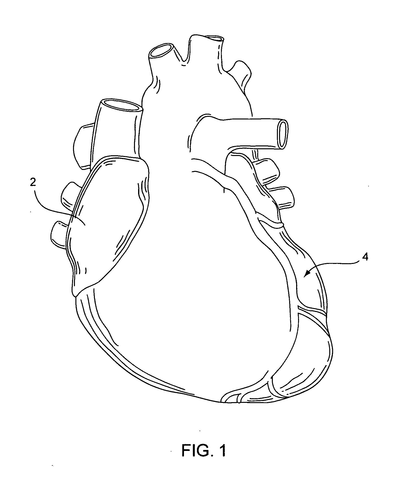
[0044] In light of this framework, FIG. 1 shows a heart 2 in which its vessels may be the subject of one or more angioplasty and / or stenting procedures. To date, however, significant difficulty or impossibility is confronted in reaching smaller coronary arteries 4. If a stent and a delivery system could be provided for...


PUM


Abstract

Medical device and methods for delivery or implantation of prostheses within hollow body organs and vessels or other luminal anatomy are disclosed. The subject technologies may be used in the treatment of atherosclerosis in stenting procedures.

Description

BACKGROUND [0001] Implants such as stents and occlusive coils have been used in patients for a wide variety of reasons. One of the most common “stenting” procedures is carried out in connection with the treatment of atherosclerosis, a disease that results in a narrowing and stenosis of body lumens, such as the coronary arteries. Typically, prior to stenting, an angioplasty procedure is performed to dilate the vessel at the site of the narrowing (i.e., the site of a lesion) by means of a balloon. Thereafter, a stent is set in apposition to the interior surface of the lumen at the lesion site in order to help maintain an open passageway. This result may be affected by means of scaffolding support alone or in coordinated use with one or more drugs carried by the stent to aid in preventing restenosis. [0002] Various stent designs exist and are in use today, but self-expandable and balloon-expandable stent systems and their related deployment techniques are now predominant. Balloon-expan...

Claims


Application Information

Patent Timeline
IPC IPC(8): A61F2/06
CPCA61F2/91A61F2/966A61F2/95
Inventor CHANG, JEAN C.
Owner BIOSENSORS INT GROUP
Why Eureka
Try Eureka