System and method for delivering a mitral valve repair device

a technology for repairing devices and mitral valves, applied in blood vessels, prostheses, medical science, etc., can solve the problems of insufficient delivery systems, inconvenient use of medical implants, and inability to fully coadjust valve leaflets,

Inactive Publication Date: 2007-03-29
EDWARDS LIFESCIENCES CORP
View PDF91 Cites 256 Cited by
  • Summary
  • Abstract
  • Description
  • Claims
  • Application Information

AI Technical Summary

Benefits of technology

[0015] In another embodiment, an apparatus for treating a mitral valve comprises a delivery catheter including an inner tubing and an outer sheath, the inner tubing having an inflatable balloon disposed along a distal end region. A handle is attached to a proximal end of the delivery catheter, the handle including a sliding button attached to the outer sheath. A self-expanding medical implant is located on the inner tubing in a contracted condition and is covered by the outer sheath. The sliding button is retractable for withdrawing the outer sheath and deploying the medical implant. The inflatable balloon preferably has a tapered distal end portion configured to extend from the outer sheath for facilitating advancement of the delivery catheter through a patient's vasculature and into a coronary sinus. The tapered distal end portion of the inflatable balloon may be coated with a lubricious coating. During delivery, at least a portion of the medical implant may be disposed over the inflatable balloon such that inflation of the inflatable balloon assists in the deployment of the medical implant.

Problems solved by technology

These geometric alterations result in incomplete coaptation of the valve leaflets during systole.
Although a number of delivery systems have been proposed for delivering medical implants, it has been found that existing delivery systems are not always adequate and are not well-suited for use with recently developed medical implant technology.

Method used


Image

  • System and method for delivering a mitral valve repair device
  • System and method for delivering a mitral valve repair device
  • System and method for delivering a mitral valve repair device

Examples


Embodiment Construction

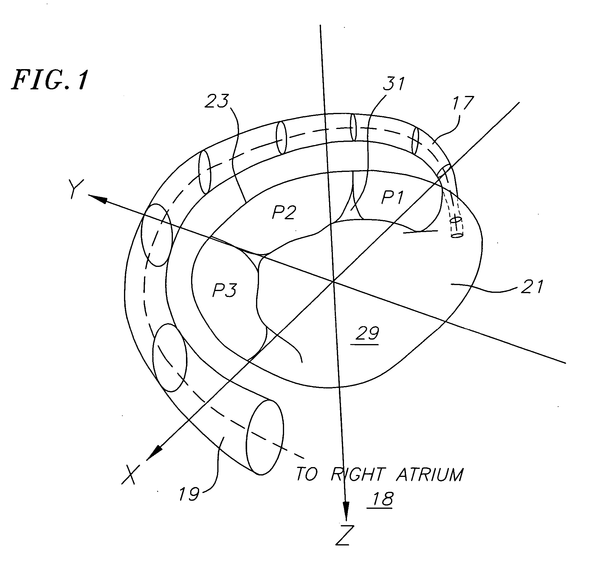
[0045] With reference now to FIG. 1, a three-dimensional view of a mitral valve 21 and a coronary sinus 17 is provided for background purposes. From this view, it can be seen that the coronary sinus extends around a posterior region of the mitral valve 21. The coronary sinus is a relatively large vessel that receives venous drainage from the heart muscle. Blood flows through the coronary sinus and empties into the right atrium 18 through a coronary ostium 19. A mitral annulus 23 is a portion of tissue surrounding a mitral valve orifice to which the valve leaflets attach. The mitral valve 21 generally includes an anterior leaflet 29 and a posterior leaflet 31. The posterior leaflet is formed with three scallops P1, P2 and P3. As used herein, the term coronary sinus 17 is used as a generic term that describes the portion of the vena return system that is primarily situated adjacent to the mitral valve 21 and extends, at least in part, along the atrioventricular groove. Accordingly, th...


PUM

PropertyMeasurementUnit
diameteraaaaaaaaaa
diameteraaaaaaaaaa
diameteraaaaaaaaaa

Abstract

A system and method is provided for treating a mitral valve. The method preferably includes advancing a guide catheter to an ostium of the coronary sinus and advancing a delivery catheter containing a medical implant through the guide catheter and into the coronary sinus. The delivery catheter has an inner member on which the medical implant is held and an outer sheath which is retractable for deploying and releasing the medical implant. In one embodiment, the medical implant has proximal and distal anchors and a bridge containing resorbable material. The inner member may have a flexible sleeve for gripping and holding a portion of the outer sheath, thereby providing a releasable attachment mechanism. In another embodiment, the inner member may include an inflatable balloon having a tapered distal region which extends from the outer sheath for providing an atraumatic tip. The inflatable balloon may also be used to expand the medical implant and to grip the outer sheath.

Description

FIELD OF THE INVENTION [0001] The present invention relates to a delivery system and method, and more particularly to a delivery system and method for delivering a mitral valve repair device. BACKGROUND [0002] Heart valve regurgitation, or leakage from the outflow to the inflow side of a heart valve, is a condition that occurs when a heart valve fails to close properly. Regurgitation through the mitral valve is typically caused by changes in the geometric configurations of the left ventricle, papillary muscles and mitral annulus. Similarly, regurgitation through the tricuspid valve is typically caused by changes in the geometric configurations of the right ventricle, papillary muscles and tricuspid annulus. These geometric alterations result in incomplete coaptation of the valve leaflets during systole. [0003] A variety of heart valve repair procedures have been proposed over the years for treating defective heart valves. With the use of current surgical techniques, it has been foun...

Claims


Application Information

Patent Timeline
Patent Type & Authority Applications(United States)
IPC IPC(8): A61F2/24A61F2/84
CPCA61F2/2451A61F2210/0004A61F2/2466
Inventor BOURANG, HENRYPINTOR, RAFAELSOLEM, JAN OTTOKIMBLAD, PER OLAHARNEK, JANFARIABI, SEPEHR
Owner EDWARDS LIFESCIENCES CORP
Why Eureka
Try Eureka