Refrigeration system with bypass subcooling and component size de-optimization

US20070074536A1Inactive Publication Date: 2007-04-05VORTEX AIRCON

Image

  • Refrigeration system with bypass subcooling and component size de-optimization
  • Refrigeration system with bypass subcooling and component size de-optimization
  • Refrigeration system with bypass subcooling and component size de-optimization

Examples


Embodiment Construction

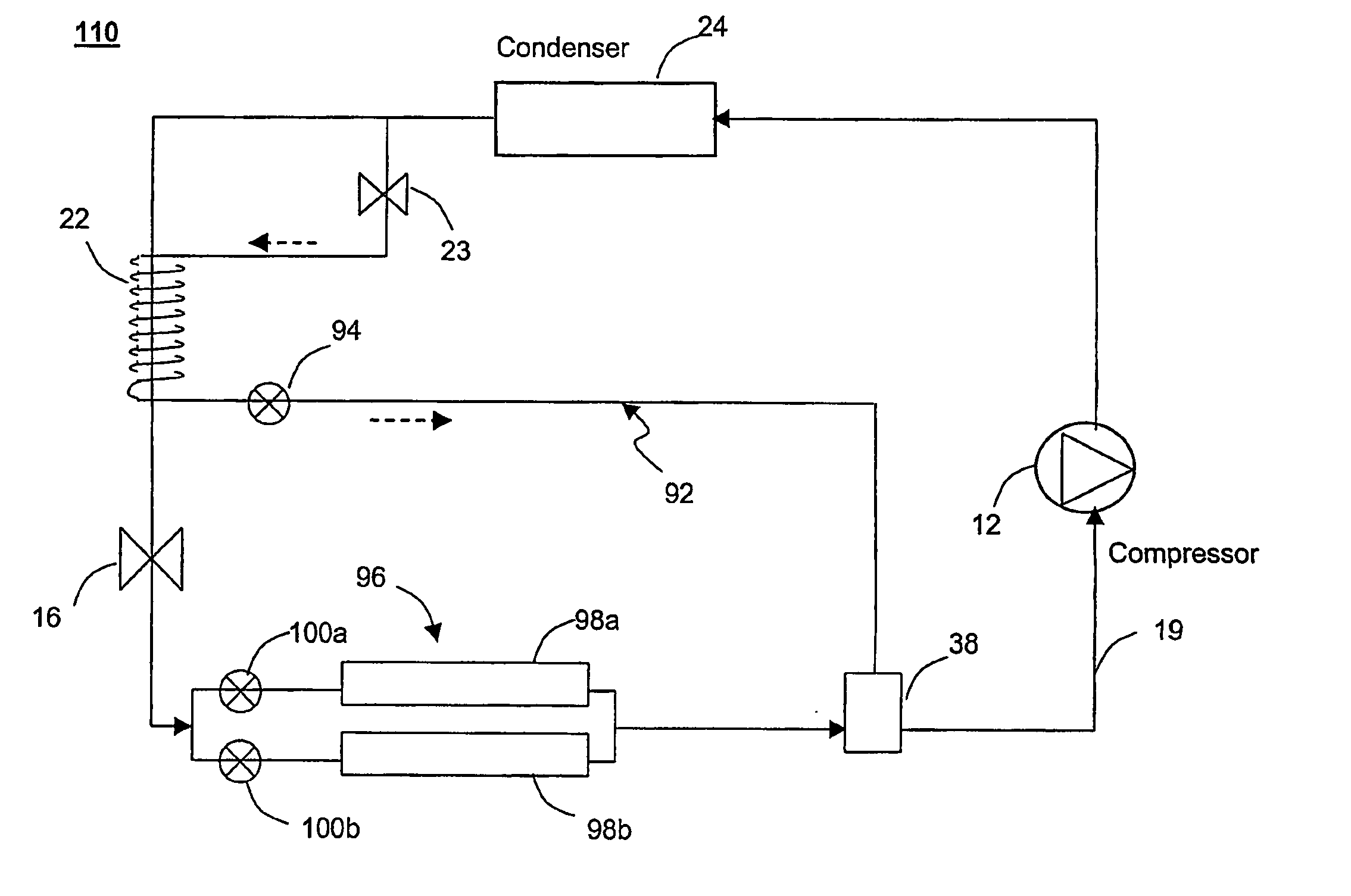
[0066]FIG. 5 shows a bypass technology concept, where a portion of liquid refrigerant is bypassed through a bypass line or path 27. The refrigerant in the bypass path goes through a secondary expansion device 23, thus lowering its pressure and temperature. The cold refrigerant mixture after the secondary expansion device receives heat energy from the hot liquid refrigerant that has exited the condenser and is flowing through the primary refrigerant line, producing additional subcooling in the liquid refrigerant. The additional subcooling produced from this bypass method makes the subcooling process in the condenser unnecessary. Thus, FIG. 5 shows a smaller condenser 14b, where the subcooling section has been removed and is identified as a dotted rectangular box.

[0067]FIG. 6 shows that the bypass technology enables the use of a larger evaporator than the evaporator in an optimized system without the bypass technology. The use of the larger evaporator is possible because of the incre...


PUM


Abstract

A refrigeration system having a primary refrigerant path including a compressor, a condenser, a primary expansion device, and an evaporator connected together to form a closed loop system with a refrigerant circulating therein; and a bypass path coupled to an outlet of the condenser. The bypass path includes a secondary expansion device; and a heat exchanger thermally coupled to the primary refrigerant path between the condenser outlet and the primary expansion device inlet to remove heat from the refrigerant discharged from the condenser. The condenser is downsized such that lacks the heat transfer capacity to provide some or all of the required subcooling as provided according to conventional practice, and the heat exchanger provides some or all the required subcooling according to the capacity of the condenser. A pressure differential accommodating device operative to mix two vapors at different pressures may also be provided to connect the outlets of the evaporator and the heat exchanger to an inlet of the compressor. A method of operating a refrigeration system with a downsized condenser and an a bypass path including a heat exchanger to provide subcooling is also described.

Description

CROSS-REFERENCE TO PRIOR APPLICATION [0001] This application claims priority to U.S. Provisional Application Ser. No. 60 / 426,073, filed Nov. 11, 2002.BACKGROUND OF THE INVENTION [0002] 1. Field of the Invention [0003] The present invention relates generally to a high efficiency refrigeration system and more specifically, to a refrigeration system utilizing a bypass path for subcooling, in combination with selection of the sizes of the condenser, compressor and evaporator, to achieve increased overall system efficiency. [0004] 2. Relevant Art [0005]FIG. 1 is a block diagram of a conventional refrigeration system, generally denoted at 10. The system includes a compressor 12, a condenser 14, an expansion device 16 and an evaporator 18. These components are connected together, typically by copper tubing such as indicated at 19 to form a closed loop system through which a refrigerant such as R-12, R-22, R-134a, R-407c, R-410a, ammonia, carbon dioxide or natural gas is cycled. [0006] The ...

Claims


Application Information

Patent Timeline
05 Apr 2007
Publication
US20070074536A1
IPC
F25B41/00; F25B9/02; F25B5/02; F25B6/04; F25B9/00; F25B40/00; F25B43/00
CPC
F25B5/02; F25B6/04; F25B9/006; F25B40/00; F25B41/00; F25B43/00; F25B2341/0011; F25B2400/13
Inventors
BAI, CHEOLHO