Manufacturing method of solar cell module, and solar cell and solar cell module

a solar cell module and manufacturing method technology, applied in the field of solar cell module manufacturing method, can solve the problems of cumbersome work, low filling rate of solar cells b>10/b> to the solar cell module b>20/b>, and reduce the use efficiency of ingots, so as to facilitate the electrical connection work of solar cells.

Active Publication Date: 2007-04-05
SANYO ELECTRIC CO LTD
View PDF8 Cites 47 Cited by
  • Summary
  • Abstract
  • Description
  • Claims
  • Application Information

AI Technical Summary

Benefits of technology

[0017] An object of the present invention is to provide a manufacturing method of a solar cell module with which an arrangement work and an electricity connection work of solar cells may be significantly facilitated even when a solar cell is divided into small pieces as shown in FIGS. 29A to 29C, as well as to provide a solar cell and a solar cell module that are advantageously applied to this method.
[0020] According to the manufacturing method of the solar cell module relating to the first aspect, the solar cells are arranged on a cell unit basis. Here, a cell unit has a rectangular or square outline. Therefore, by arranging the cell units with one sides of the outlines matching each other, the cell units may be easily arranged in parallel both lengthwise and breadthwise.
[0021] Therefore, according to the present invention, it is possible to arrange the cell units or the solar cells that constitute a cell unit in directions of both rows and columns smoothly with a simple operation. Further, because the solar cells are arranged ona cell unit basis, it is possible to improve workability in the arrangement of the cells in comparison with a case in which the solar cells are arranged on a cell basis. Moreover, because the solar cells are previously connected with the first inter connecters when constructing a cell unit, it is possible to facilitate the electricity connection work of the solar cells in comparison with a case in which the solar cells are electrically connected while arranging the solar cells. In addition, it is possible to suppress occurrence of misalignment in the arrangement of the solar cells.
[0024] Here, the first electrode is disposed so that, when matching a oblique line of the solar cell with a oblique line of another solar cell, first electrodes on the two solar cells are aligned along a first straight line that is parallel to an arrangement direction of the two solar cells. By this arrangement, it is possible to easily connect the first electrodes on the two solar cells with the first inter connecter when constructing the cell unit.
[0025] Further, the second electrode is disposed so that, when constructing a cell unit having a rectangular outline by matching the oblique lines of the two solar cells each other and arranging two cell units in parallel with long sides of the two cell units matching each other, the second electrodes on the respective cell units are aligned along a second straight line that is parallel to an arrangement direction of the cell units. By this arrangement, when connecting the two cell units arranged parallely with the long sides of the two cell units matching each other, it is possible to easily connect the second electrodes on the respective cell units with the second inter connecter.

Problems solved by technology

In recent years, against the backdrop of problems such as depletion of petroleum resources and global warming, development and spread of clean energy source without using petroleum resources have been taken up as a global-scale challenge.
This results in a problem that a filling rate of solar cells 10 to the solar cell module 20 becomes low due to a large area of spaces between the solar cells, even when the solar cells are arranged in a manner most efficiently as shown in (a-1) of FIG. 28, for example.
However, at the same time, this causes a problem that an unused area in the ingot 30 (hatched area in (b-2) of FIG. 28) that is not used as the substrate 31 becomes large, thus considerably decreasing use efficiency of the ingot.
In producing a solar cell module, a cumbersome work is required in order to arrange the solar cells and to connect electrically between the cells that have been arranged.
In particular, when the solar cell is divided into four small pieces as shown in FIG. 29C, the arrangement becomes even more cumbersome compared to the arrangement of solar cells as they are without dividing.
In this case, a problem arises that determination as to which type of the cell should be arranged at a certain position becomes difficult when arranging the four types of the solar cells in the solar cell module.

Method used


Image

  • Manufacturing method of solar cell module, and solar cell and solar cell module
  • Manufacturing method of solar cell module, and solar cell and solar cell module
  • Manufacturing method of solar cell module, and solar cell and solar cell module

Examples


configuration example 1

1. Configuration of Solar Cell

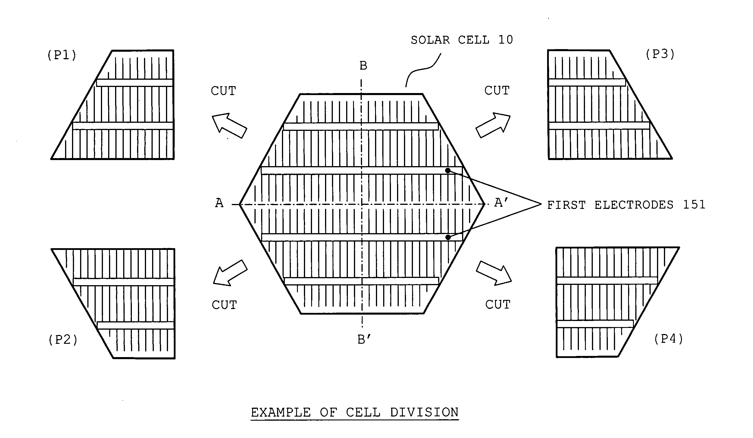
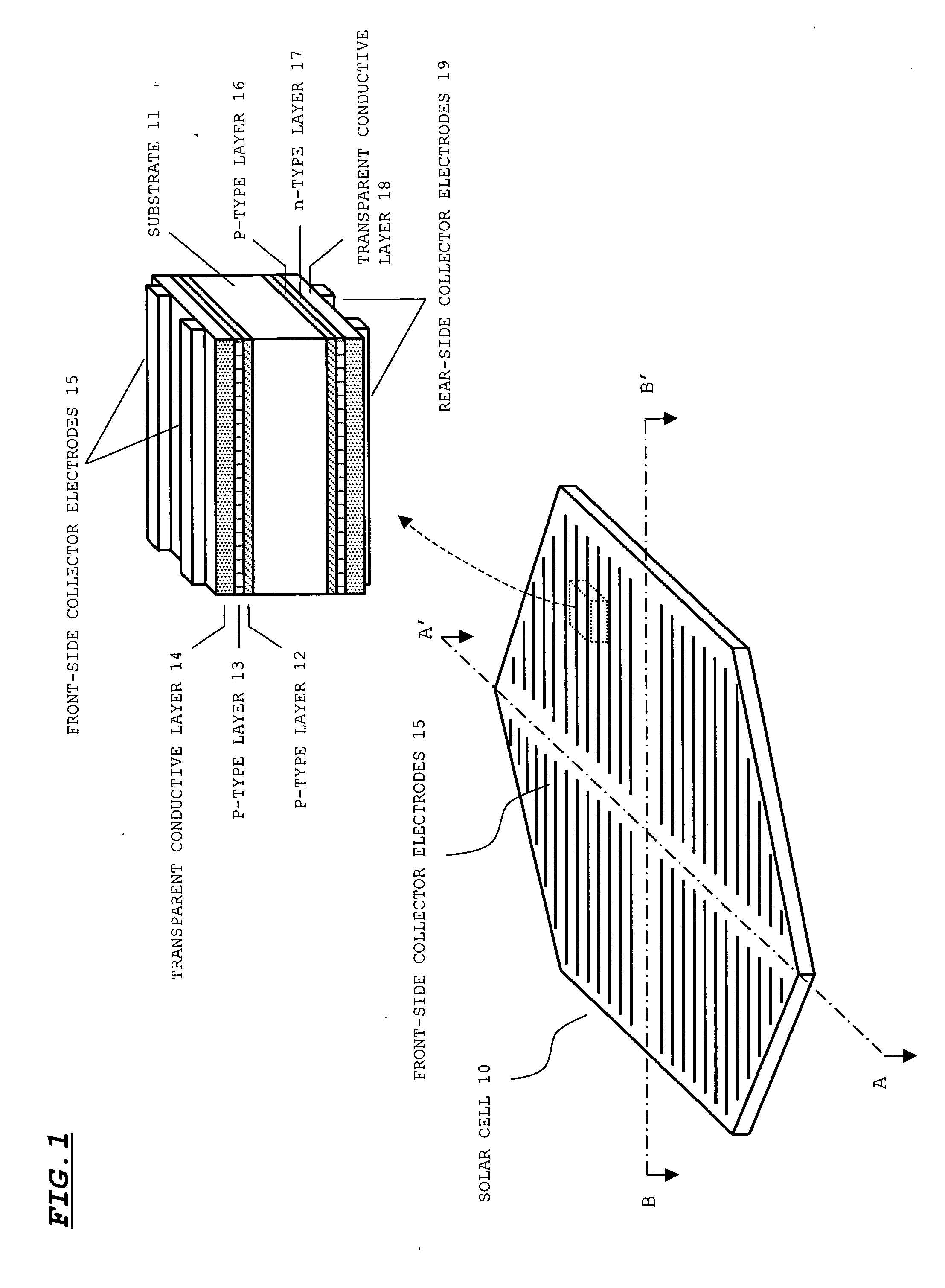
[0066]FIG. 1 illustrates a configuration of a solar cell before being divided into four pieces. As shown in the figure, a solar cell 10 is in a shape of a planer regular hexagon, and collector electrodes 15 and 19 are formed on a front surface and a rear surface, respectively, of the cell. Although not shown in FIG. 1, the solar cell 10 is also provided with electrodes (described later) respectively on the front surface and the rear surface, and these electrodes further collect photovoltaic current collected by the collector electrodes 15 and 19.

[0067] A cross-sectional configuration of the solar cell 10 is shown on the upper right of FIG. 1. As shown in this figure, the solar cell 10 includes a substrate 11, an i-type layer 12, a p-type layer 13, a transparent electrode film 14, the front-side collector electrode 15, an i-type layer 16, an n-type layer 17, a transparent conductive layer 18, and the rear-side collector electrode 19.

[0068] The substr...

configuration example 2

1. Configuration of Solar Cell

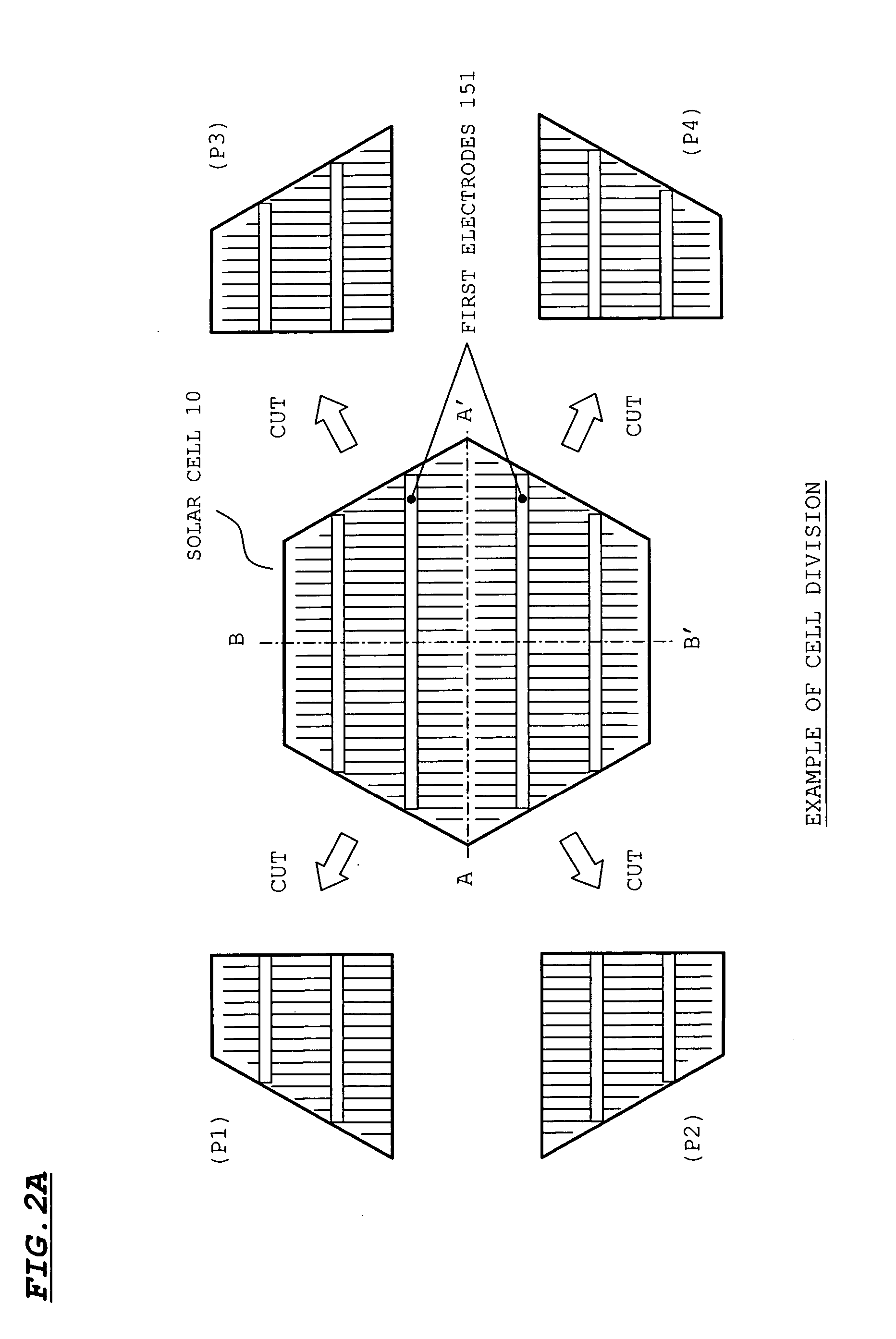
[0087]FIG. 5 illustrates another configuration example of a solar cell and a divided cell. The structure of the layers in this solar cell is the same as the structure shown in FIG. 1, other than the direction of arrangement of the collector electrode 15. According to this configuration example, the front-side collector electrode 15 and the rear-side collector electrode 19 extend in a direction perpendicular to the extension direction in the case of FIG. 1 (A-A′ in FIG. 5). Further, the first electrodes 151 are configured to be electrically connected to the front-side collector electrode 15 and the rear-side collector electrode 19. Although the first electrodes 151 are each configured so as to extend continuously from the one end to the other end of the solar cell 10 in FIG. 5, the first electrodes 151 may be divided at positions corresponding to the line A-A′ into an upper part and a lower part, so that gaps are provided at the positions corresponding...


PUM


Abstract

A double-side light receiving solar cell in a planer regular hexagon shape and having first electrodes on both surfaces are divided into four pieces by a line A-A′ connecting two opposing apexes and by a line B-B′ perpendicular to the line A-A′ and connecting center points on two opposing sides. By matching oblique lines of two divided pieces without misalignment and with respective surfaces in an inversed state, the first electrodes on the same side of the two divided pieces align along the same single straight line. Then, the first electrodes that are on the same side are connected with a first inter connecter, thereby constructing a unit having a rectangular outline. Units thus constructed are arranged so that relevant sides match without misalignment. By handling on a unit basis as described above, it is possible to facilitate an arrangement of the cells and an electricity connection work.

Description

[0001] This application claims priority under 35 U.S.C. §119 of Japanese Patent Application No. 2005-288181 filed Sep. 30, 2005. BACKGROUND OF THE INVENTION [0002] 1. Field of the Invention [0003] The present invention relates to a manufacturing method of a solar cell module, and to a solar cell and a solar cell module. In particular, the present invention is suitable to be applied to a solar cell module containing double-side light receiving solar cells in which sunlight may incident from front and rear faces of them, and a manufacturing method thereof and a solar cell to be applied to such solar cell module. The present invention is suitably applicable also to the solar cell module which contains not double-side light receiving solar cells but one-side light receiving solar cells. [0004] 2. Description of the Related Art [0005] In recent years, against the backdrop of problems such as depletion of petroleum resources and global warming, development and spread of clean energy sourc...

Claims


Application Information

Patent Timeline
Patent Type & Authority Applications(United States)
IPC IPC(8): H02N6/00H01L31/00
CPCH01L31/035281H01L31/042H01L31/0504Y02E10/547H01L31/05
Inventor YAGIURA, TOSHIOOKAMOTO, SHINGONAKAUCHI, ATSUSHI
Owner SANYO ELECTRIC CO LTD
Why Eureka
Try Eureka