Freewheel bearing device with torque limiter

a freewheel bearing and torque limiter technology, applied in the field of bearings, can solve the problems of relatively large drive, structural and functional differences of the torque limiter and the freewheel, and achieve the effects of reducing space requirements, and reducing the risk of breakag

Inactive Publication Date: 2007-04-05
SKF FRANCE
View PDF74 Cites 17 Cited by
  • Summary
  • Abstract
  • Description
  • Claims
  • Application Information

AI Technical Summary

Benefits of technology

[0027] Advantages of the freewheel bearing devices described herein include that the space requirement of the device is limited and it has the shape of a compact, preassembled cartridge relatively well protected against the outer elements. The lifetime of the moving parts upstream and downstream of the freewheel is lengthened thanks to the smoothing of the torque peaks, hence more economical running and a reduced risk of breakage.

Problems solved by technology

However, this torque limiter is structurally and functionally different from a freewheel, because the free rotation of one race relative to the other race is not possible.
Such a drive is however relatively bulky.

Method used


Image

  • Freewheel bearing device with torque limiter
  • Freewheel bearing device with torque limiter
  • Freewheel bearing device with torque limiter

Examples


Embodiment Construction

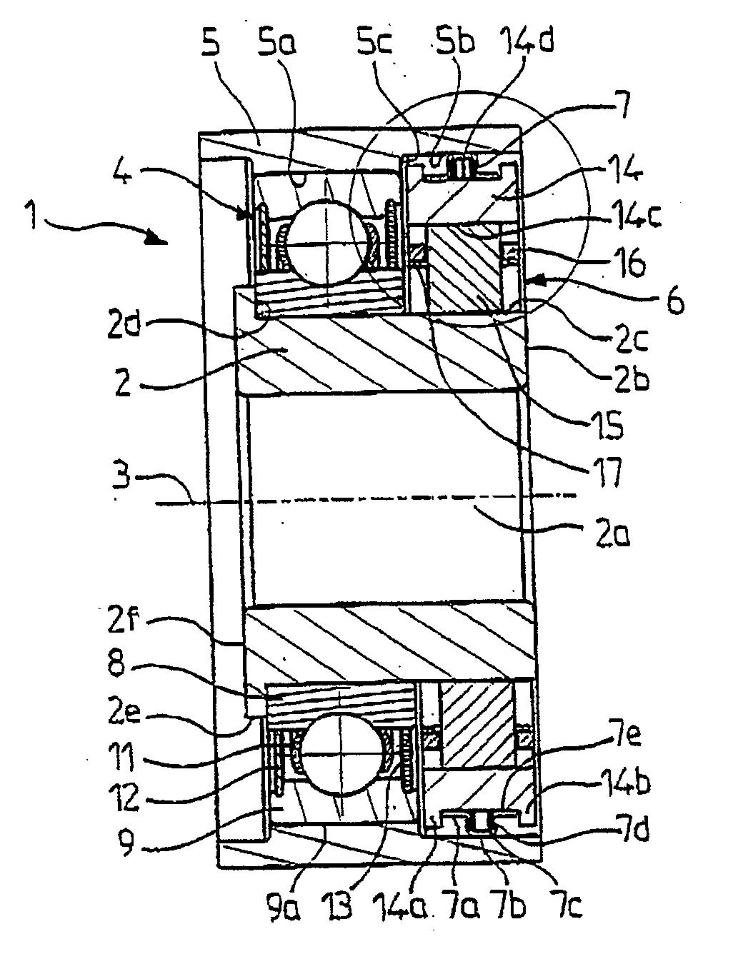
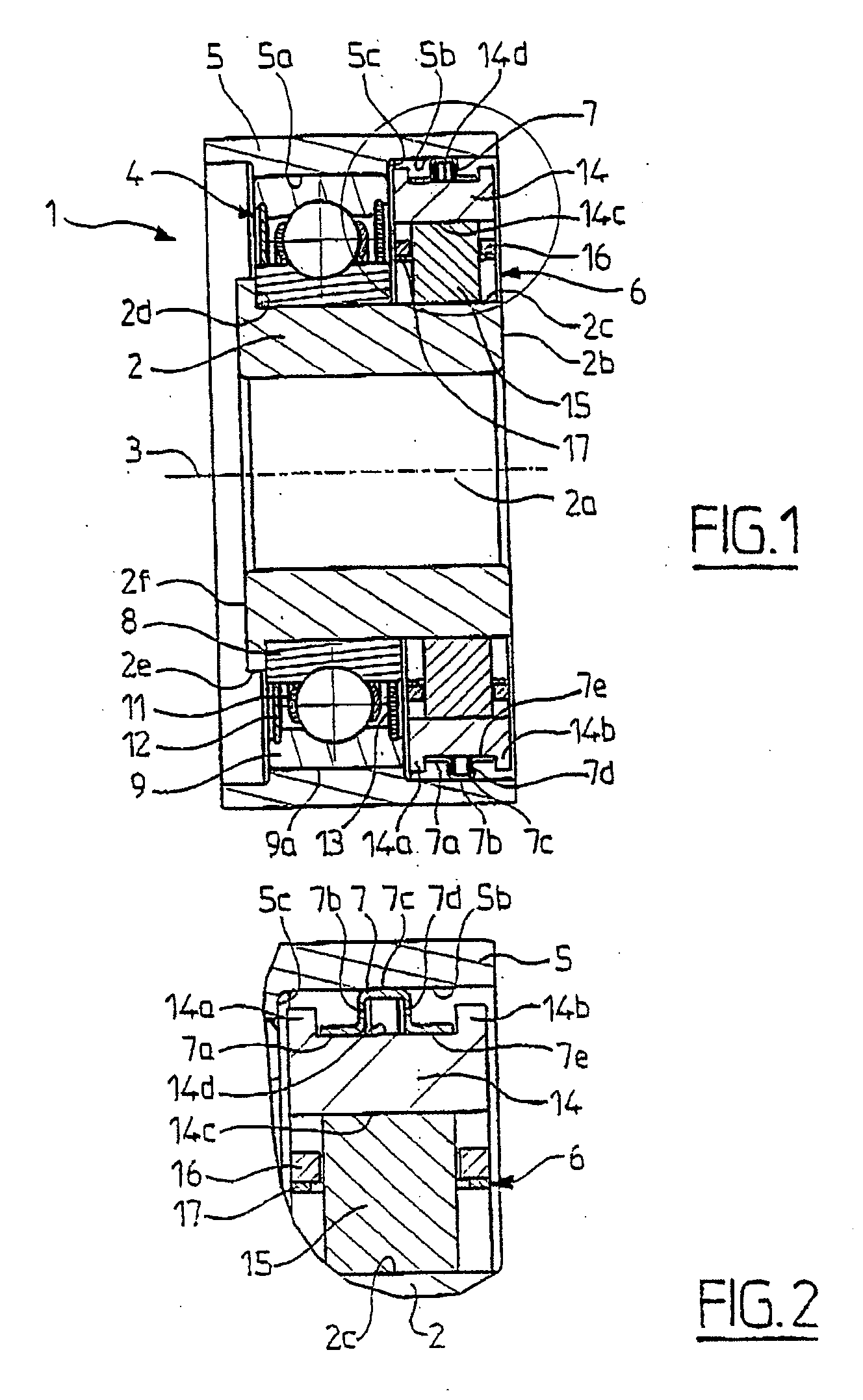
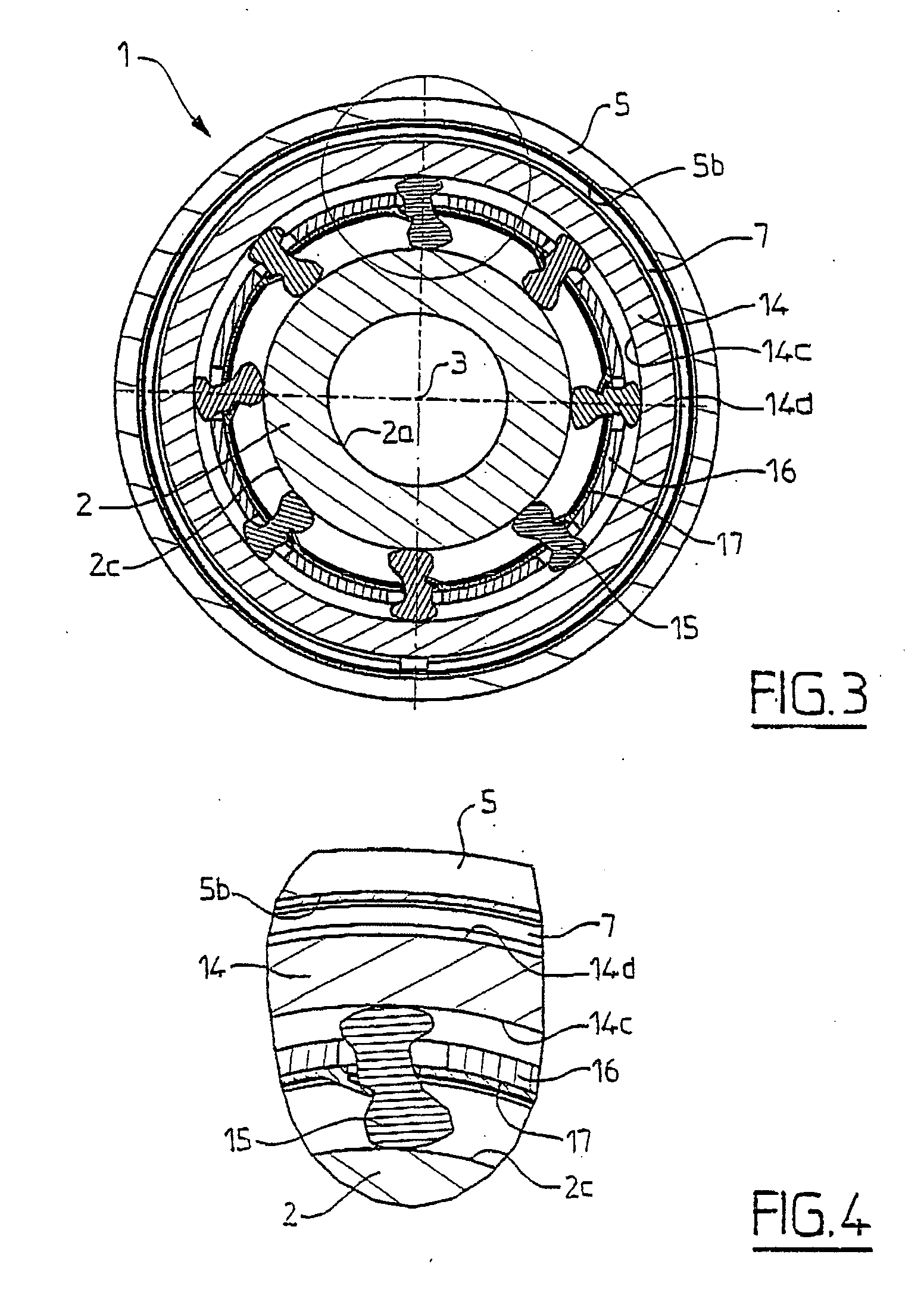
[0046] As can be seen in FIGS. 1 to 4, the freewheel device, reference number 1 in its entirety, includes a tubular sleeve 2 with its axis 3, a rolling bearing 4 mounted on the sleeve 2, an outer element 5 mounted on the rolling bearing 4, a freewheel 6 mounted on the sleeve 2 and a friction element 7 mounted between the outer element 5 and the freewheel 6.

[0047] The sleeve 2 includes a bore 2a, a transverse radial surface 2b, an outer cylindrical surface 2c extending over the major part of its length from the end radial surface 2b, a radial surface 2d extending toward the outside from the end of the outer cylindrical surface 2c, a short axial surface 2e extending from the free end of the radial portion 2d, axially opposite the end radial surface 2b, and an end radial surface 2f opposite the end radial surface 2b.

[0048] The rolling bearing 4 may be of a standard type, with a low production cost and includes a solid inner race 8 provided with a bore mounted, for example by sleeve-fi...


PUM


Abstract

The invention concerns a freewheel bearing device including an outer element and inner element arranged inside the outer element, and a free wheel provided with at least a wedging element, arranged between the inner element and the outer element to allow a free rotational movement in one direction between the outer element and the inner element and for transmission of a torque in the other direction between the outer element and the inner element, the free wheel including a ring provided with a cylindrical inner surface and a cylindrical outer surface, substantially aligned on a radial plane perpendicular to the axis of rotation of the device, and a torque limiting member adapted to limit the torque transmitted by the free wheel, the torque limiting member being arranged radially between said ring and the outer element or the inner element in contact with said ring and said element.

Description

BACKGROUND OF THE INVENTION [0001] 1. Field of the Invention [0002] The present invention relates to the field of bearings comprising a unidirectional clutch or freewheel, usually interposed between an inner element and an outer element. [0003] 2. Description of the Relevant Art The freewheel makes it possible to transmit a torque in one direction and to allow a relative rotation in the other direction. A bearing may also be interposed between the inner element and the outer element to support radial and, where necessary, axial loads. Document FR A 2 726 059 describes a device of this kind. [0004] Also known is document GB-A-2 259 962 which describes a torque limiter making it possible to limit the torque to different values depending on the direction of rotation of one race relative to the other race, by means of friction balls in one direction and a spring in the other direction. However, this torque limiter is structurally and functionally different from a freewheel, because the ...

Claims


Application Information

Patent Timeline
Patent Type & Authority Applications(United States)
IPC IPC(8): F16D41/00F16D7/02F16D41/07F16D41/20F16D43/21
CPCF16D7/021F16D41/07F16D41/206F16D43/211F16C19/06F16C41/001
Inventor PONSON, FREDERICPULLE, THIERRYHAMADA, VIRGINIELESCORAIL, ROMUALDCAILLAULT, CLAUDE
Owner SKF FRANCE
Why Eureka
Try Eureka