Freewheel coupling

a freewheel and clutch technology, applied in the direction of clutches, freewheel clutches, brake types, etc., can solve the problem of not completely fixed relative radial position of the cage, and achieve the effect of good resistance to oils

Inactive Publication Date: 2007-04-05
SCHAEFFLER TECH AG & CO KG
View PDF6 Cites 6 Cited by
  • Summary
  • Abstract
  • Description
  • Claims
  • Application Information

AI Technical Summary

Benefits of technology

[0011] The cage of the freewheel coupling is preferably made from plastic. In an especially advantageous configuration, a fiber-reinforced plastic, especially a glass fiber-reinforced plastic, is used for the production of the cage. In this way, a temperature resistance up to approximately 200° and also good resistance to oils common in the automotive field can be achieved.
[0012] As long as no radial loads act on the cage, it is preferably guided inwards, namely onto the spring band. Alternatively, an outer guide of the cage is also possible. The ends of the spring band are preferably arranged overlapping radially within the single cage of the freewheel coupling without a connection. Because each clamping body is mounted in a cage pocket so that it can move, in a preferred configurat

Problems solved by technology

Likewise, the radial position of the cage is no

Method used


Image

  • Freewheel coupling
  • Freewheel coupling
  • Freewheel coupling

Examples


Embodiment Construction

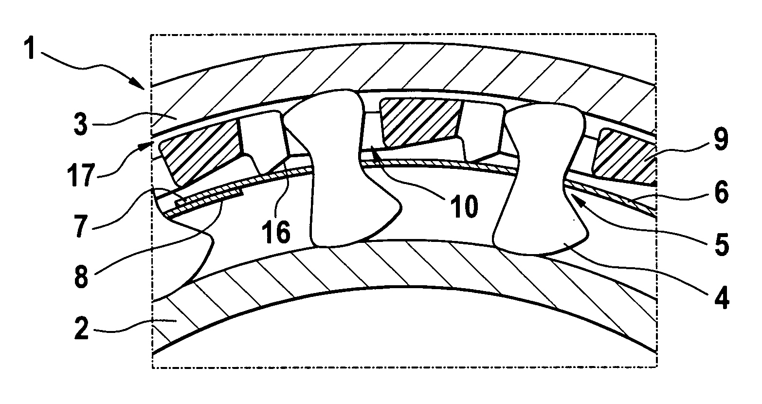
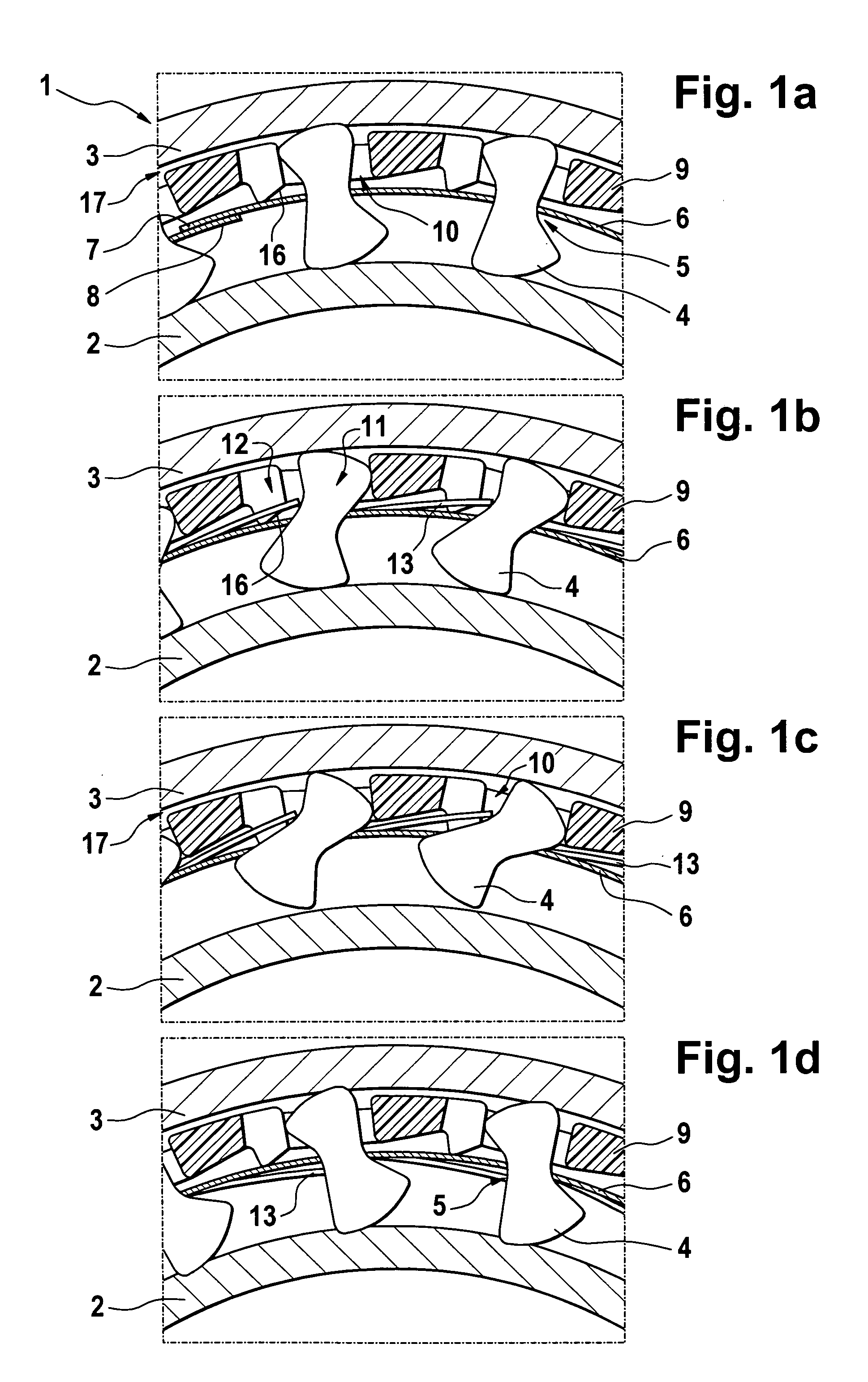
[0018]FIGS. 1a to 1d show, in section, simplified cross-sectional illustrations of a freewheel coupling 1, also designated as a clamping body freewheel, in different states of conventional operation. The freewheel coupling 1 is used, for example, in a torque converter or in an automatic transmission of a motor vehicle. In the torque converter, the freewheel coupling 1 can guarantee a freewheel function for the guide wheel arranged between the pump wheel and the turbine wheel.

[0019] The essential components of the freewheel coupling 1 are an inner ring 2 and an outer ring 3, between which several clamping bodies 4 are arranged. The clamping bodies 4 have a reduced-size shape with a narrow section 5, with these narrow sections 5 determining the position of a spring band 6 arranged essentially concentrically to the inner ring 2 and outer ring 3. The spring ends 7, 8 not connected to each other overlap, as follows from FIG. 1a. Radially between the spring band 6 and the outer ring 3 th...


PUM


Abstract

A freewheel coupling (1) is provided having clamping bodies (4), which are arranged between an inner ring (2) and an outer ring (3) and which have a narrow section (5). A single cage (9) is arranged between the inner ring (2) and the outer ring (3) with a plurality of pockets (10). Each of the pockets (10) has an area (12) that is narrower in the axial direction and an area (11), which is adjacent to this narrower area, which is wider in the axial direction, and which is provided for holding a clamping body (4). A spring band (6), which is arranged radially within the cage (9), has an original curvature in the unloaded state, wherein the curvature radius exceeds a radius of the cage (9), and spring tongues (13), which are provided for spring mounting of the clamping bodies (4), are directed radially inwardly.

Description

FIELD OF THE INVENTION [0001] The invention relates to a freewheel coupling or overrunning clutch with reduced-size clamping bodies arranged between an inner ring and an outer ring. BACKGROUND OF THE INVENTION [0002] A freewheel coupling of the above-noted type is known, for example, from DE 103 10 225 A1. This freewheel has clamping bodies, which can be tilted to a limited degree in a cage, with a positive-fit stop for the clamping bodies, as well as for a spring tongue contacting the clamping bodies on one boundary wall of the cage, being provided when the clamping body is tilted in the direction towards the raised, non-clamping position. The spring tongue has either a so-called bending geometry (see FIG. 1, FIG. 5) or extends in the tangential direction of the freewheel without a bending geometry (see FIG. 6). While the former embodiment requires a relatively high production-related expense, for the latter embodiment, higher forces can appear in the spring in the tangential direc...

Claims


Application Information

Patent Timeline
IPC IPC(8): F16D41/07
CPCF16D41/07
Inventor STRAUB, FRANKALTMANN, FRIEDER
Owner SCHAEFFLER TECH AG & CO KG
Why Eureka
Try Eureka