Switching regulator duty cycle control in a fixed frequency operation

a voltage regulator and fixed frequency technology, applied in the direction of electric variable regulation, pulse automatic control, modulation, etc., can solve the problem of frequency hysteresis, troublesome audible noise, and difficulty in achieving a very high and/or very low switch-on duty cycle, etc. problem, to achieve the effect of increasing the duty cycle of the clock oscillator

Active Publication Date: 2007-04-05
ANALOG DEVICES INT UNLTD
View PDF25 Cites 18 Cited by
  • Summary
  • Abstract
  • Description
  • Claims
  • Application Information

AI Technical Summary

Benefits of technology

[0029] It is an object of the invention to increase the duty cycle of the clock oscillator of a PWM system operating in a voltage regulator without skipping cycles and without abrupt mode changes.

Problems solved by technology

As the clock cycle rate increases, and, consequently, the clock cycle time decreases, it becomes difficult to achieve a very high and / or a very low switch-ON duty cycle as operating conditions may at times require.
One problem with this approach is that it often generates troublesome audible noise because of a low frequency modulation phenomenon associated with the cycle skipping.
The disadvantage of this is that a frequency hysteresis is needed to switch back to the other mode when the duty cycle reduces and the abrupt mode change sometimes cause system frequency instability.

Method used


Image

  • Switching regulator duty cycle control in a fixed frequency operation
  • Switching regulator duty cycle control in a fixed frequency operation
  • Switching regulator duty cycle control in a fixed frequency operation

Examples


Embodiment Construction

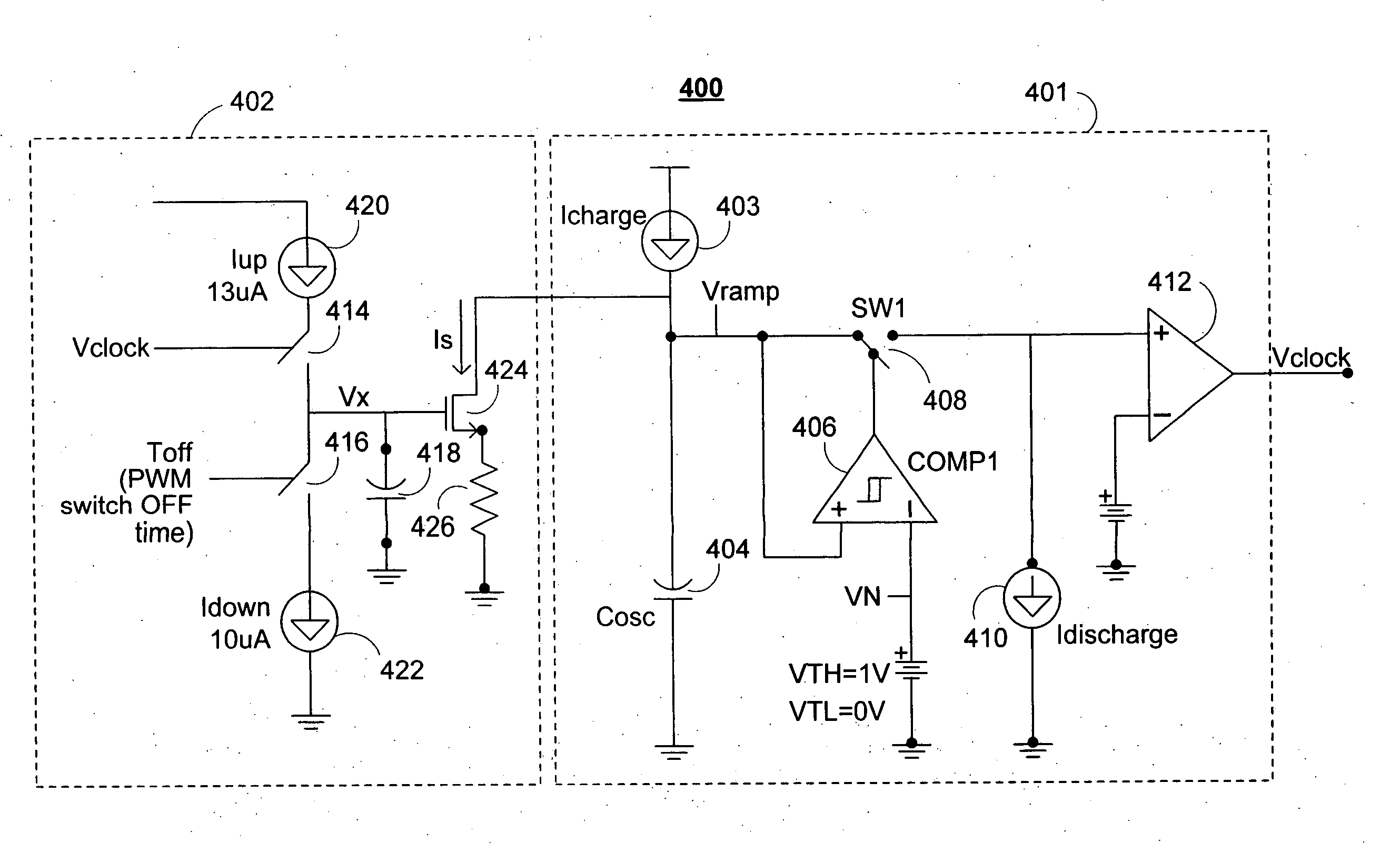
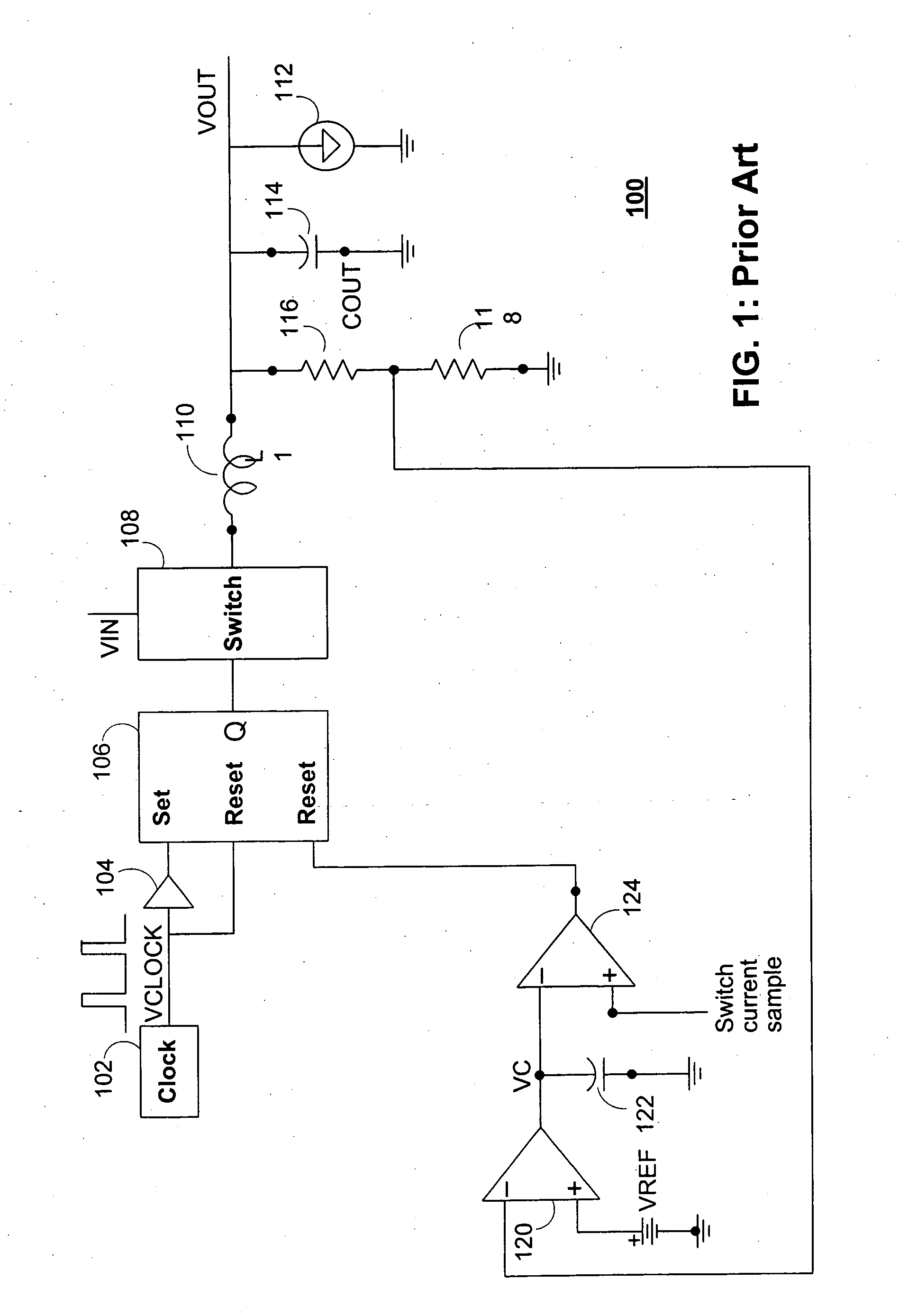
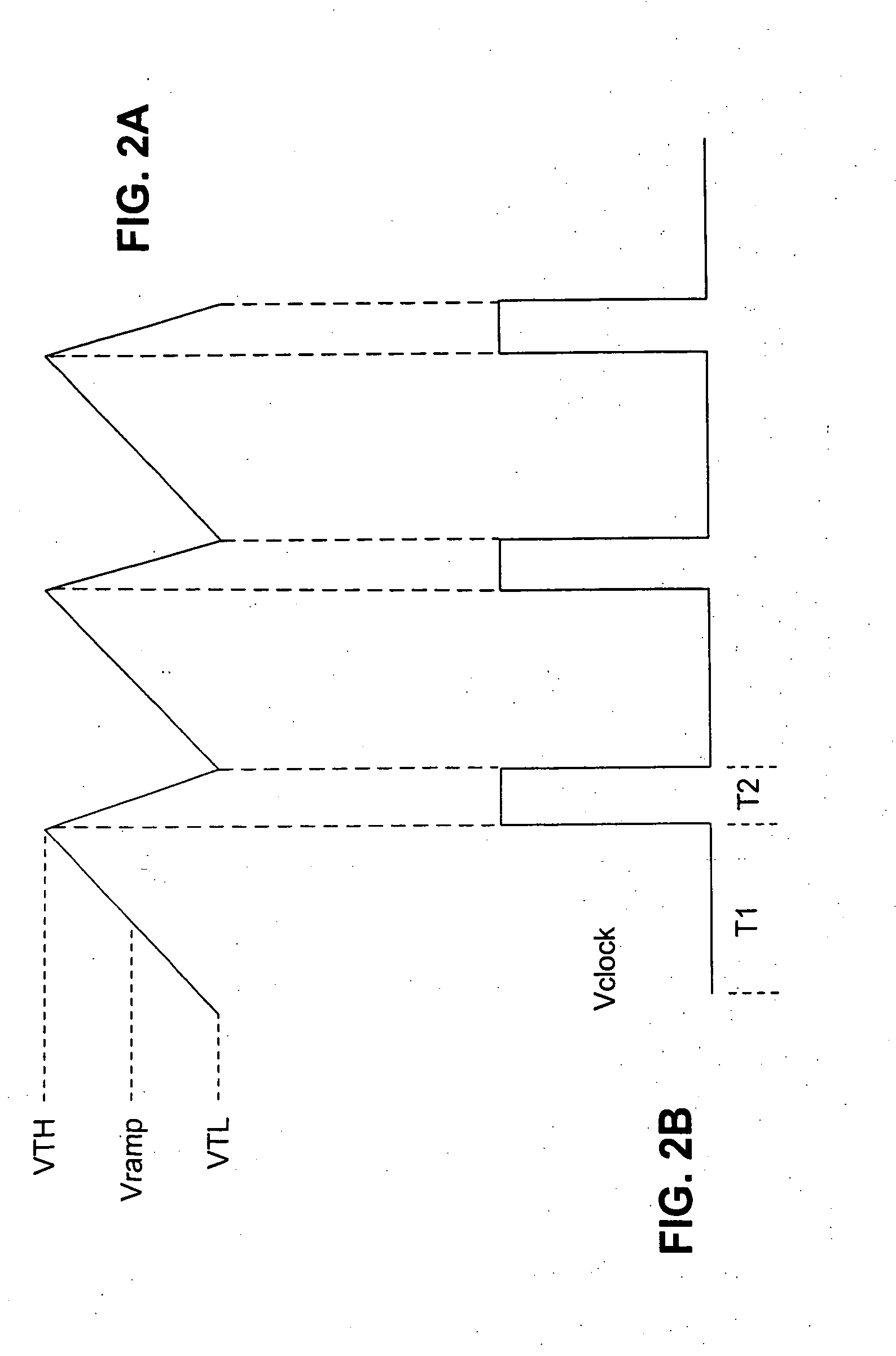
[0041] The preferred embodiment of the invention preferably provides systems and methods for operating the switch at a duty cycle of higher than 90% (or some other suitable, preferably predetermined, duty cycle ratio). The preferred embodiment of the invention can obtain these higher duty cycles in a voltage regulator similar to the exemplary regulator shown in FIG. 1 without cycle skipping. In order to accomplish this, the circuit according to the invention preferably resets every switching cycle, as will be described, and incorporates an analog feedback loop within the clock oscillator system of the PWM system to extend duty cycle time by keeping switch-OFF time constant while increasing switch-ON time.

[0042] The circuit sets a reference time of a duration T3, which is preferably slightly longer than T2 and compares the PWM switch OFF time, Toff, with T3. As the VIN / VOUT condition requires a duty cycle higher than 90%, the clock oscillator PWM switch turns ON until it is forced t...


PUM


Abstract

A clock oscillator system for use in providing the switching regulator duty cycle control in a fixed frequency (no cycle skipping) operation is provided. In one embodiment, the circuit according to the invention uses an analog feedback loop to extend the switch ON time of the clock cycle by controlling the oscillator charging current and, thereby, increase the duty cycle. Preferably, this circuit can achieve very high switching duty cycle and/or very low switching duty cycle in a PWM switching regulator operated in very low drop-out operation when very high duty cycle is required or in other conditions when very low duty cycle is required.

Description

BACKGROUND OF THE INVENTION [0001] This invention relates to voltage regulators. In particular, this invention relates to switch-mode voltage regulators. [0002] Switch-mode regulators, or switching regulators as they are commonly known, are typically used as voltage regulators because they exhibit higher efficiency than an equivalent linear regulator circuit at heavy loads. A typical switching regulator operates by repeatedly turning a power switch fully on and then fully off, generating a pulse-width modulated signal that is averaged to the final voltage with an inductor. [0003] For simplicity, the present invention is particularly described in a step-down converter embodiment. Nevertheless, the invention is not limited to this particular embodiment and, in fact, may be implemented on any suitable switching regulator. The basic invention, as well as alternative implementations of the invention, will be discussed in more detail below. [0004]FIG. 1 shows a basic, conventional switchi...

Claims


Application Information

Patent Timeline
Patent Type & Authority Applications(United States)
IPC IPC(8): H03B5/12H03L7/099
CPCH02M3/156H03K7/08H03K4/50
Inventor LIAO, CHIAWEI
Owner ANALOG DEVICES INT UNLTD
Why Eureka
Try Eureka