Optical tomography system

a tomography system and optical technology, applied in the field of optical tomography system, can solve the problems of inability to obtain tomographic image thereof, deterioration of the s/n of the detected interference signal, and enlarged spatial frequency of the interference signal, so as to achieve easy switching, widen the measurable range (measuring depth) and easy to find.

Active Publication Date: 2007-04-05
KK TOPCON +1
View PDF4 Cites 4 Cited by
  • Summary
  • Abstract
  • Description
  • Claims
  • Application Information

AI Technical Summary

Benefits of technology

[0010] In view of the foregoing observations and description, the primary object of the present invention is to provide an optical tomography system where a tomographic information is obtained by projecting the measuring light onto the object while sweeping at the wavelength of the measuring light and carrying out frequency-analysis on the interference light at that time which can be switched in its measurable range (measuring depth) according to the application and is improved in convenience.
[0028] When the first detecting mode is an image obtaining mode for obtaining a tomographic image of the object and the second detecting mode is a measurement initiating position adjusting mode in which the position in the direction of depth of the object in which tomographic image signal is to be obtained is adjusted, since the wavelength resolution can be increased in the measurement initiating position adjusting mode so that the measurable range (measuring depth) is broadened and the object can be easily found, the object can be apt to be obtained as a tomographic image in the measurement initiating position adjusting mode and the measurement initiating position can be efficiently adjusted.

Problems solved by technology

However, there arises a problem that when the optical path length difference becomes large, the spatial frequency of the interference signal is enlarged and the S / N of the detected interference signal deteriorates due to limitation on the sampling time of the photodiodes such as CCDs for detecting the interference light.
Similarly, there is a problem that when layer structure such as of the stomach wall is to be observed, the tomographic image thereof cannot be obtained due to the measurable range (measuring depth).

Method used


Image

  • Optical tomography system
  • Optical tomography system
  • Optical tomography system

Examples


Embodiment Construction

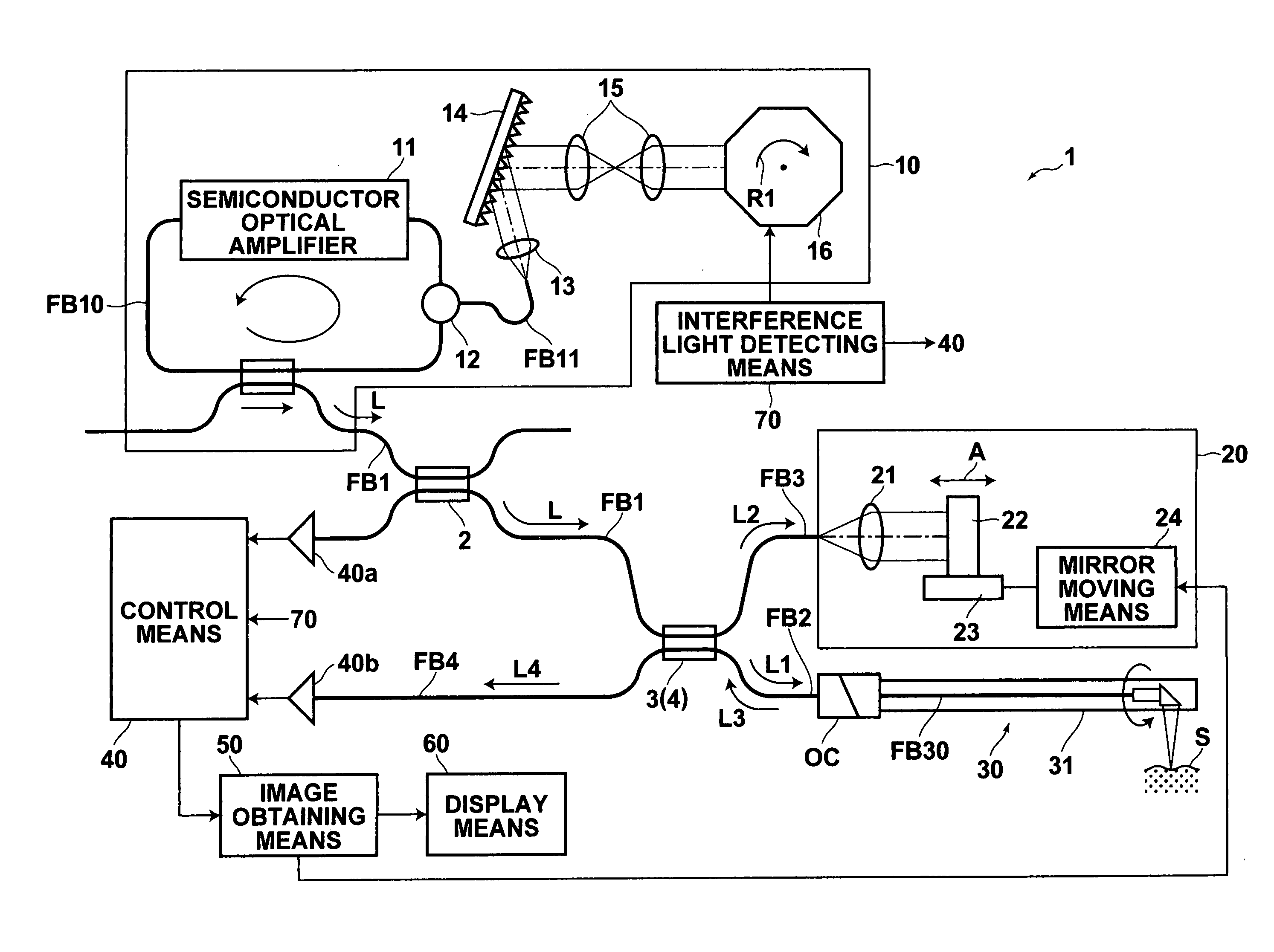
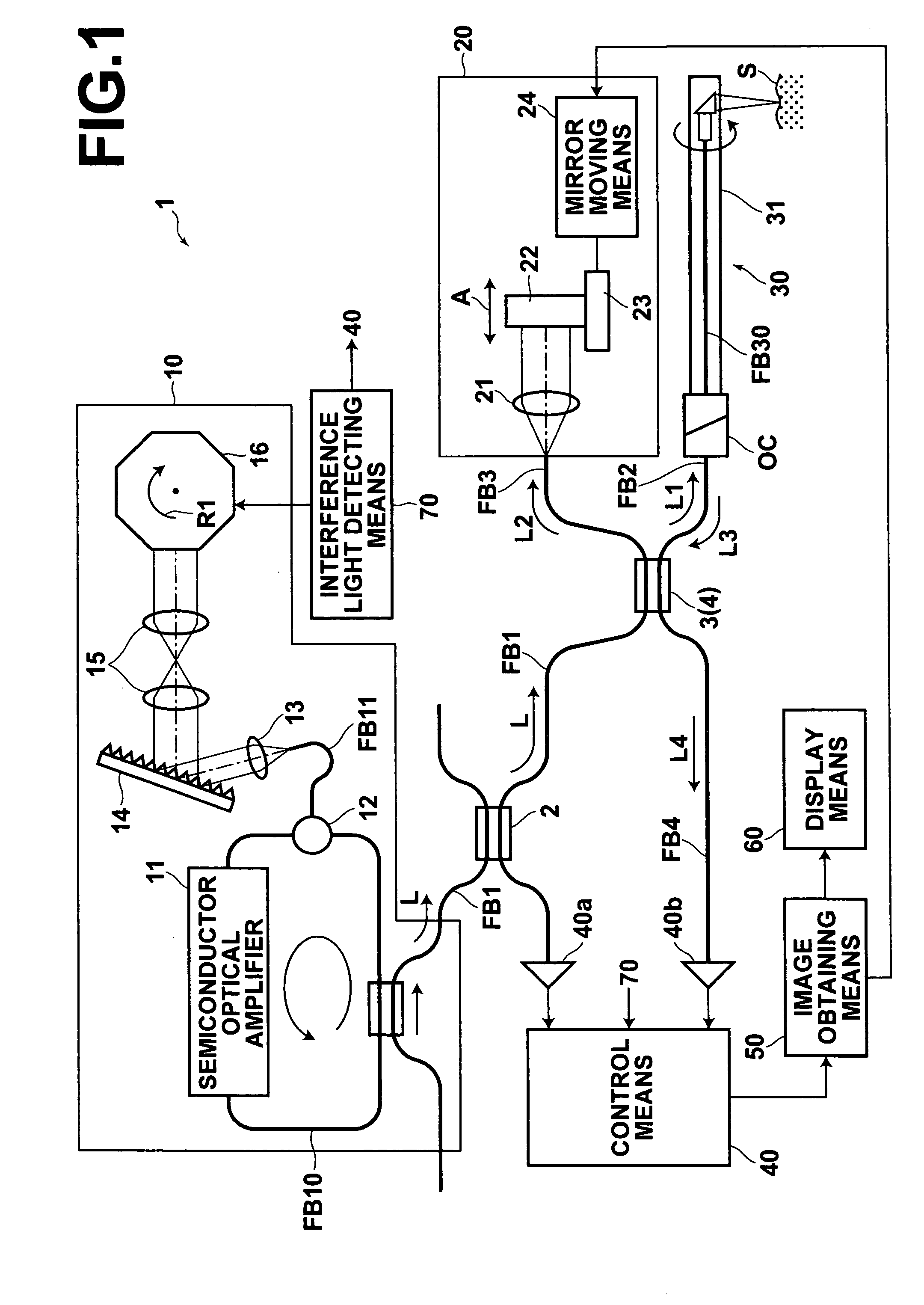
[0034] Embodiments of the optical tomography system of the present invention will be described in detail with reference to the drawings, hereinbelow. FIG. 1 is a schematic diagram that illustrates an optical tomography system in accordance with a preferred embodiment of the present invention. The optical tomography system 1 of this embodiment is for obtaining a tomographic image of an object of measurement such as a living tissue or a cell in a body cavity by measuring the SS-OCT. The optical tomography apparatus 1 of this embodiment comprises: a light source unit 10 for emitting a laser beam L; a light dividing means 3 for dividing the laser beam L emitted from the light source unit 10 into a measuring light beam L1 and a reference light beam L2; an optical path length adjusting means 20 for adjusting the optical path length of the reference light beam L2 divided by the light dividing means 3; a probe 30 which guides to the object S to be measured the measuring light beam L1 divide...


PUM


Abstract

In an optical tomography system for obtaining a tomographic image of an object to be measured by detecting interference light of the reflected light and the reference light, a controller switches between a first detecting mode in which the interference light is detected at a first wavelength resolution and a second detecting mode in which the interference light is detected at a second wavelength resolution higher than the first wavelength resolution.

Description

BACKGROUND OF THE INVENTION [0001] 1. Field of the Invention [0002] This invention relates to an optical tomography system for obtaining an optical tomographic image by measurement of OCT (optical coherence tomography). [0003] 2. Description of the Related Art [0004] As a system for obtaining a tomographic image of an object of measurement in a body cavity, there has been known an ultrasonic tomography system. In addition to such an ultrasonic tomography system, there has been proposed an optical tomography system where an optical tomographic image is obtained on the basis of an interference of light by low coherence light. See, for instance, Japanese Unexamined Patent Publication No. 2003-172690. In the system disclosed in Japanese Unexamined Patent Publication No. 2003-172690, an optical tomographic image is obtained by measuring TD-OCT (time domain OCT) and the measuring light is guided into the body cavity by inserting a probe into the body cavity from the forceps port of an end...

Claims


Application Information

Patent Timeline
Patent Type & Authority Applications(United States)
IPC IPC(8): G01B11/02G01J3/45G01B9/02
CPCA61B5/0073G01N21/4795G01B9/02004G01B9/02091G01B9/02048G01B9/02089A61B5/0066
Inventor KAWAHARA, KARIN
Owner KK TOPCON
Why Eureka
Try Eureka