Image processing apparatus

a technology of image processing and apparatus, which is applied in the direction of digital output to print units, multi-programming arrangements, instruments, etc., can solve the problems of reducing the compatibility of cpu programs, increasing circuit scale, and increasing processing unit overhead, so as to shorten the processing time of the entire system, improve processing performance, and facilitate activation

Inactive Publication Date: 2007-04-05
SOCIONEXT INC
View PDF6 Cites 8 Cited by
  • Summary
  • Abstract
  • Description
  • Claims
  • Application Information

AI Technical Summary

Benefits of technology

[0046] According to this configuration, since states other than completed states of the processing units can be determined based upon the state dependence table, it is possible to produce a more flexible activation condition so as to shorten processing time of the entire system, leading to improvement in processing performance.
[0047] According to the image processing apparatus of the present invention, the circuit scale of each of the processing units can be reduced. Further, the processing speed can be improved. Namely, the overhead of the processing units can be reduced to improve the parallelism between the control unit and the processing units.
[0048] The CPU is capable of executing parameter calculation for a next sequence without interrupt during operations of the control unit and each of the processing units, so as to improve the processing efficiency.
[0049] Even when the interface of the processing unit is changed, the change does not affect the CPU program, thereby enabling enhancement in compatibility of the CPU program.

Problems solved by technology

However, the above-mentioned method requires every processing unit to have a parameter reading mechanism, which increases address management scale, data lines, and the like, resulting in an increase in circuit scale.
For the management of states of the other processing units, a signal line needs to be added to between the processing units, which necessitates control of state update timing and the like, leading to an increase in overhead of the processing units.
Moreover, even when the order of activation of each processing unit is intended to be changed, the CPU program needs to be changed, thereby reducing the compatibility of the CPU program.
Therefore, the CPU needs to operate in synchronization with processing completion of each of the processing units, which makes it difficult to improve the parallelism between the CPU and each of the processing units.

Method used


Image

  • Image processing apparatus
  • Image processing apparatus
  • Image processing apparatus

Examples


embodiment 1

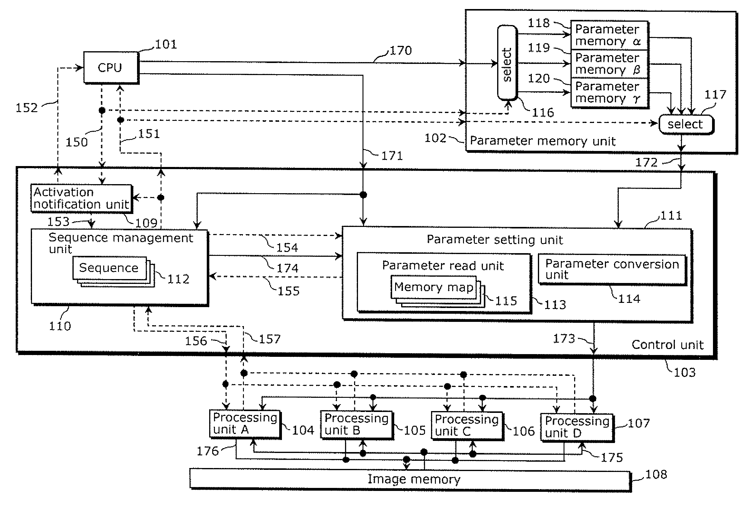
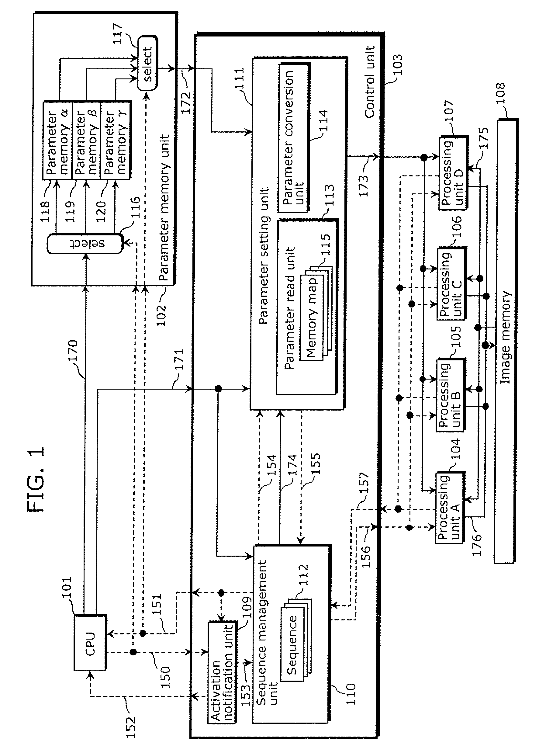
[0088]FIG. 1 is a block diagram showing a configuration of an image processing apparatus in Embodiment 1 of the present invention. This image processing apparatus comprises a CPU 101, a parameter memory unit 102, a control unit 103, a processing unit A104, a processing unit B105, a processing unit C106, a processing unit D107, and a memory 108. These components may form one chip of a system LSI or the components excluding the memory 108 may form one chip. The parameter memory unit 102 comprises three memory regions (parameter memory a118, parameter memory β119, parameter memory γ120), a data write selector 116, and a data read selector 117. The control unit 103 comprises an activation notification unit 109, a sequence management unit 110, and a parameter setting unit 111.

[0089] The CPU 101 calculates parameters necessary in operations of the processing unit A104, the processing unit B105, the processing unit C106 and the processing unit D107, and the parameters are transferred to t...

embodiment 2

[0112]FIG. 9 shows a block diagram showing a configuration of an image processing apparatus in Embodiment 2 of the present invention. In FIG. 9, the same elements as in FIG. 1 are provided with the same symbols as in FIG. 1, and the description thereof is omitted. In Embodiment 2, the data line which transfers the sequence identifier and the memory map identifier directly from the CPU 101 to the control unit 103 is not present, but a data line is present which transfers the sequence identifier and the memory map identifier through the parameter memory unit 102.

[0113] The CPU 101 calculates a parameter necessary for operation of each of the processing units, and transfers the parameter to the parameter memory unit 102 through the use of a data line 270 for transfer of a parameter sequence identifier and a memory map identifier. Further, along with the parameter, the CPU 101 transfers the sequence identifier and the memory map identifier to the parameter memory unit 102.

[0114] Upon ...

embodiment 3

[0117]FIG. 11 is a block diagram showing a configuration of an image processing apparatus according to Embodiment 3 of the present invention. In FIG. 11, the same elements as in FIG. 9 are provided with the same symbols as in FIG. 9, and the description thereof is omitted. In Embodiment 3, an identifier determination unit 301 is present.

[0118] The CPU 101 calculates a parameter necessary for operation of each of the processing units, and transfers the parameter to the parameter memory unit through the use of a data line 370 for transfer of a parameter identifier and a processing identifier. Further, simultaneously with the parameter, the CPU 101 transfers a processing identifier to the parameter memory unit 102.

[0119] Upon receipt of the sequence activation signal 153, the sequence management unit 110 reads a processing identifier from the parameter memory unit 102 out to the identifier determination unit 301 through the use of a data line 371 for transfer of a sequence identifier...


PUM


Abstract

An image processing apparatus of the invention includes: a plurality of processing units which share image processing; a parameter memory unit which holds a parameter specifying an operation of each of the processing units; and a control unit which controls the plurality of processing units, and the control unit includes: a sequence management unit which activates each of the processing units according to a sequence indicating a sequence of activation of and completion of processing by each of the processing units, and confirms completion of the processing; and a parameter setting unit which, in advance of activation of each of the processing units by the sequence management unit, reads a parameter for each processing unit to be activated, from the parameter memory unit according to a memory map indicating an address of the parameter for the processing unit, and sets the parameter to the processing unit according to the read result.

Description

BACKGROUND OF THE INVENTION [0001] (1) Field of the Invention [0002] The present invention relates to an image processing apparatus used for image filtering processing, an image codec and the like. [0003] (2) Description of the Related Art [0004] With the significant technological progress of digital video equipments in recent years, there are increasing opportunities to perform image processing such as image compression / decompression processing and filtering. In the case of performing such image processing, an image processing apparatus is often used in which processing is divided and the divided processing operations are performed in parallel in a plurality of processing units. However, in the middle of the technological competition, such an image processing apparatus is strictly restricted in terms of processing performance and an amount of memory used, and the image processing is increasing in complexity along with the technological progress. [0005] In the case of parallel opera...

Claims


Application Information

Patent Timeline
Patent Type & Authority Applications(United States)
IPC IPC(8): G06F3/12
CPCG06F9/5027G06F9/52G06F2209/5017G06T1/20H04N19/42G06F9/522
Inventor TERADA, KENGOOTOMURA, EIJINAKAJIMA, KOUJISAKAMOTO, AKIRA
Owner SOCIONEXT INC
Why Eureka
Try Eureka