
Microelectronic positioning for bioparticles

a bioparticle and micro-electronic technology, applied in biochemistry, biochemical apparatus and processes, enzymes, etc., can solve the problems of unbalanced nutrient supply, the inability to make cells uniformly position and distribute, and the inability to make cells. to be easily displaced and distributed

Inactive Publication Date: 2007-04-05
IND TECH RES INST
View PDF3 Cites 2 Cited by
  • Summary
  • Abstract
  • Description
  • Claims
  • Application Information

AI Technical Summary

Benefits of technology

[0007] One objective of the present invention is to provide a method for positioning bioparticles, which utilizes dielectric and non-contact electrical force of cell themselves associated with multi-phase electric signals to attain uniformity of cell distribution and nutrient supply in a cell culture system.
[0009] It is another objective of the present invention to provide a method for positioning bioparticles, which can programmably change cell's position and remove cell's clamping at any time so that it is very advantageous for collection and redistribution of cell products.
[0011] In another aspect, the present invention provides a method for controlling uniform distribution of bioparticles, which comprises providing a cell culture system with an electrode array provided therein, where the electrode array includes several electrode groups and each electrode group has a plurality of adjacent electrodes; introducing a liquid containing bioparticles in the cell culture system; and simultaneously applying a plurality of AC signals unto each of the electrode groups, wherein each of the AC signals is added unto one electrode of the electrode group to make the two AC signals applied unto each two adjacent electrodes have the same voltage and the same frequency but have different phases, so that the bioparticles can position uniformly with electric forces.

Problems solved by technology

In a vessel culture system, cells can obtain fresh nutrient supply from liquid medium; the way to make cells positioning and distribution uniformly becomes a major issue.
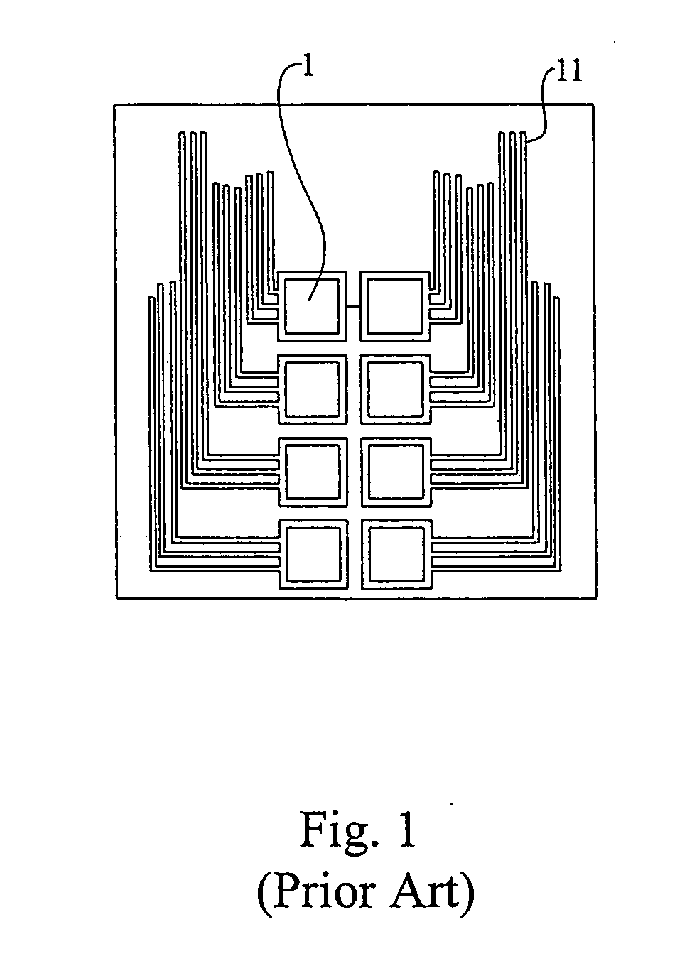
Although each cell culture room 1 disclosed in U.S. Pat. No. 6,653,124 can control nurturing environment individually, but it still has problems about dead places from sluggish floating medium, unbalanced nutrient supply, and cell deformation from extruding.
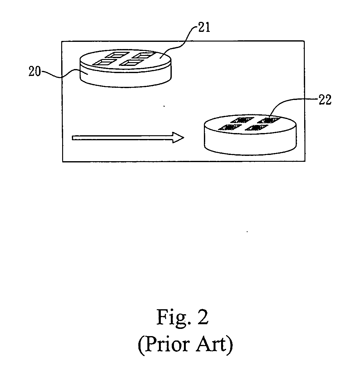
Although the method can precisely position a group of cells in the openings, but can not control the uniformity of distribution of the cells.
The method disclosed in U.S. Pat. No. 5,795,457 uses non-mechanical and non-contact force to position cells, but it can not confirm uniformity of the cell distribution.
But this method also can not confirm uniformity of the cell distribution.

Method used


Image

  • Microelectronic positioning for bioparticles
  • Microelectronic positioning for bioparticles
  • Microelectronic positioning for bioparticles

Examples


first example

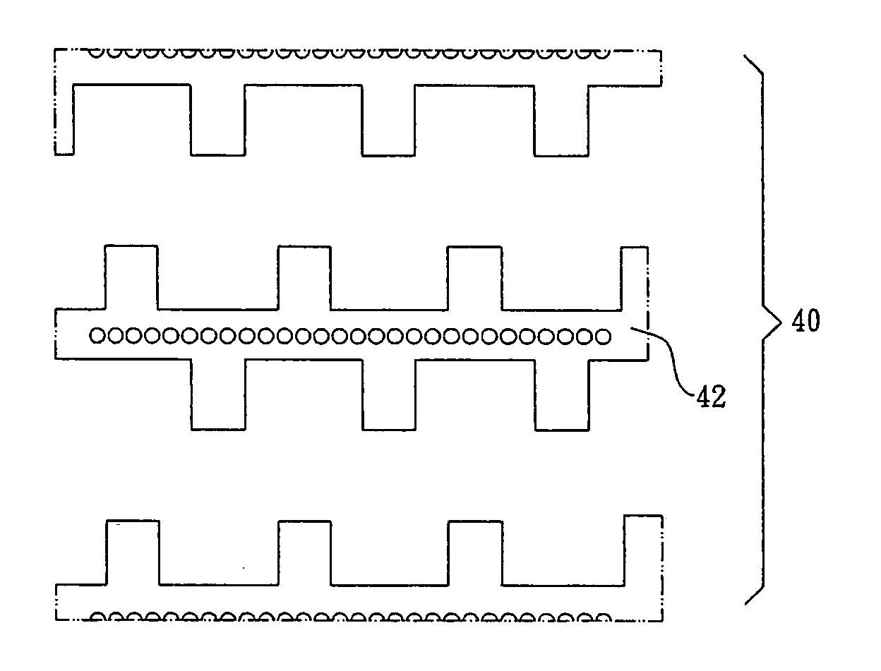
[0023] In the first example, an electrode array 40 is set on an inner sidewall of a vessel cell culture system (not shown). The electrode array 40 is composed of a plurality of parallel interdigitated castellated electrodes 42. First, the latex particle solution is introduced into the vessel cell culture system, and then the adjacent interdigitated castellated electrodes 42 are applied with the first AC signal with 0 degree phase and the second AC signal with 180 degree phase individually. The first AC signal and the second AC signal are both have 20 KHz frequency and 14 Vpp voltage, and the conductivity of the latex particle solution is 1×10⁻⁴ S / m. Referring to FIG. 4, the latex particles will gather on the central portion of the interdigitated castellated electrodes.

second example

[0024] Different from the first example, the second example changes the phase of the second AC signal to 90 degree. As such, the adjacent interdigitated castellated electrodes 42 are applied with the first AC signal with 0 degree phase and the second AC signal with 90 degree phase. The first AC signal and the second AC signal are both have 20 KHz frequency and 20 Vpp voltage, and the conductivity of the latex particle solution is 1×10⁻⁴ S / m. Referring to FIG. 5, the result reveals that the latex particles gather in the space between the adjacent teeth-like electrodes of the same interdigitated castellated electrode 42, and the latex particles periodically gather in the space without electrodes.

[0025] According to the above examples, the present invention can apply AC signals with different phases unto adjacent electrodes individually. As such, the latex particles can gather in particular regions so as to reach electric positioning.

third example

[0026] In the third example, an electrode array 60 is set on an inner sidewall of the vessel cell culture system. The electrode array 60 is divided to a plurality of electrode groups 62, and each electrode group 62 has four adjacent electrodes 622. Four AC signals with 0 degree, 90 degree, 180 degree and 90 degree phase are individually applied unto one of the four adjacent electrodes 622 of each electrode group 62 so that each of the adjacent electrodes 622 has the AC signal with different phase applied thereupon. Each electrode 622 has 24 KHz frequency and 18 Vpp Voltage, and the conductivity of the latex particle solution is 1×10⁻⁴ S / m. Referring to FIG. 6, under such the circumstance, the latex particles produce violent vibrations, and thus the latex particles uniformly distribute.


PUM

PropertyMeasurementUnit
Angleaaaaaaaaaa
Timeaaaaaaaaaa
Forceaaaaaaaaaa

Abstract

The present invention provides a method for microelectronic positioning bioparticles, which utilizes dielectric and non-contact electrical force of cell themselves associated with multi-phase electrical signals to attain uniformity of distribution of the bioparticles and positioning thereof within micro-areas in a cell culture system. The obstacle of system geometrical structure is eliminated so as to simplify the system layout and programmably change cells' positions. The present method is suitable for treating cell array in a large quantity. The present method utilizes electrical control for the cells. The clamping of the cells can be removed at any time. It is very advantageous for collection and redistribution of cell products.

Description

BACKGROUND OF THE INVENTION [0001] 1. Field of the Invention [0002] The present invention relates to a method for positioning bioparticles, and more particularly to a method for controlling distribution and positions of the bioparticles with multi-phase electrical signals. [0003] 2. Description of the Related Art [0004] In a vessel culture system, cells can obtain fresh nutrient supply from liquid medium; the way to make cells positioning and distribution uniformly becomes a major issue. Referring to FIG. 1, U.S. Pat. No. 6,653,124 discloses a vessel cell culture system. The vessel cell culture system has a plurality of individual arrayed cell culture rooms 1, and each cell culture room 1 has its own nutrient supply micro-channels 11. Although each cell culture room 1 disclosed in U.S. Pat. No. 6,653,124 can control nurturing environment individually, but it still has problems about dead places from sluggish floating medium, unbalanced nutrient supply, and cell deformation from extr...

Claims


Application Information

Patent Timeline
IPC IPC(8): C12N15/09
CPCC12M35/02
Inventor YU, TUNG-MING
Owner IND TECH RES INST
Learn More