
Quadrature voltage controlled oscillator

a voltage control and oscillator technology, applied in the direction of oscillator generators, electrical equipment, radio transmission, etc., can solve the problems of driving up licensing costs for a specific frequency, and affecting the accuracy of iq signals,

Inactive Publication Date: 2007-04-05
SAMSUNG ELECTRO MECHANICS CO LTD
View PDF10 Cites 12 Cited by
  • Summary
  • Abstract
  • Description
  • Claims
  • Application Information

AI Technical Summary

Benefits of technology

[0055] The operations and effects of the invention will be explained in detain with reference to the accompanying drawings.
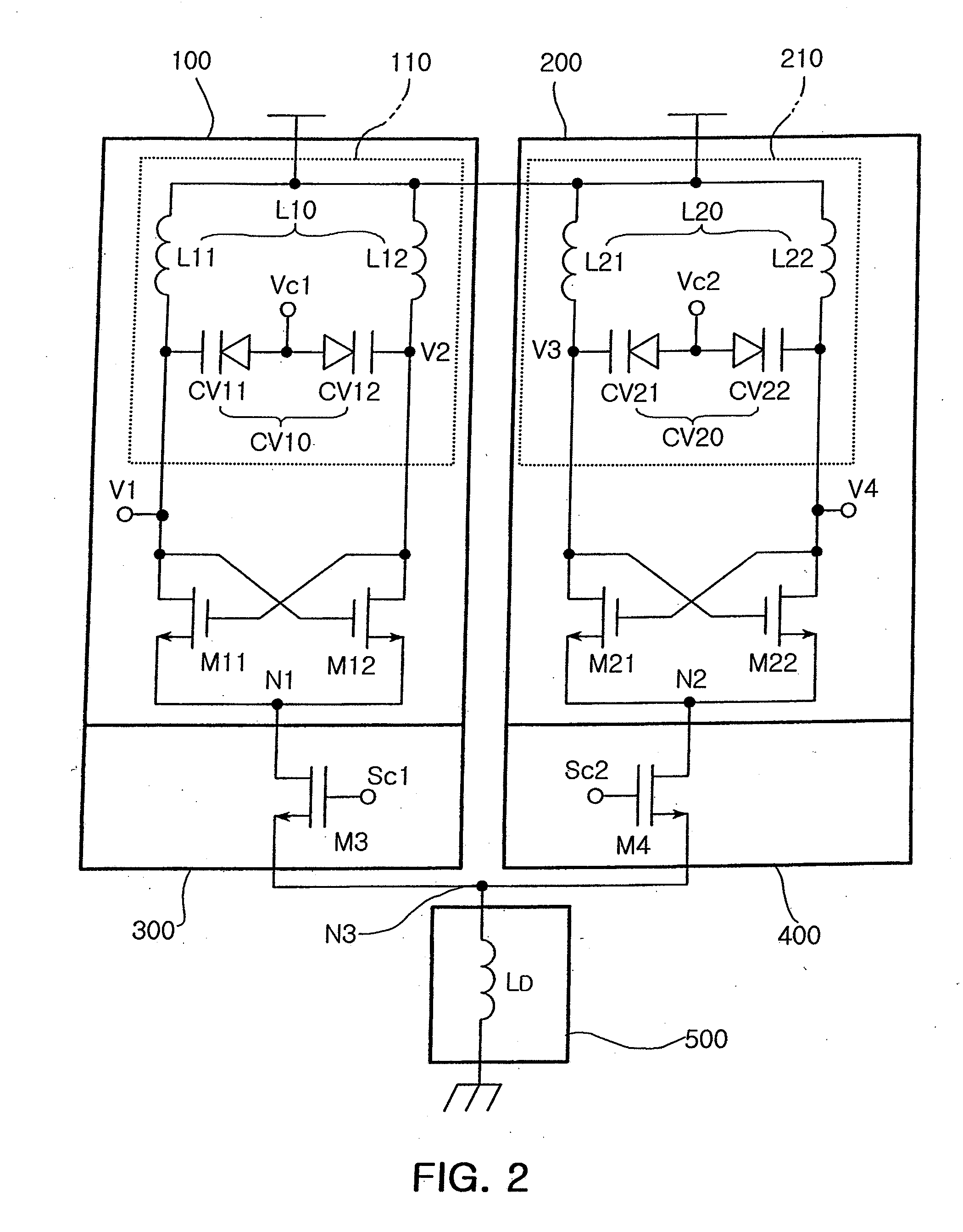
[0056] The quadrature voltage controlled oscillator of the invention differentiates a quadrature signal using an inductor, thereby not generating phase noises and more ensuring the quadrature signal to be differential. A detailed explanation will be given with reference to FIGS. 2 to 4.
[0057] Referring to FIG. 2, first, the first oscillator 100 of the quadrature voltage controlled oscillator of the invention generates first and second signals V1 and V2 which are 180 degree out of phase with each other. In

Problems solved by technology

But a limited available frequency is driving up licensing costs for a specific frequency.
Specifically, first, in case of employing a VCO and a frequency distributor, a duty cycle of the VCO less than 50% renders the I / Q signals inaccurate.
Here, typically loads of the frequency distributor act as resistances, which however are so differently sized that the accuracy of the IQ signals is compromised.
Second, in case of employing a VCO and a multi-phase filter, an amplifier is necessarily added due to significant signal loss, thereby resulting in great additional power consumption.
Third, in case of employing two separate VCOs and coupling, a coupling transistor is utilized to couple the VCOs, thereby increasing phase noises.
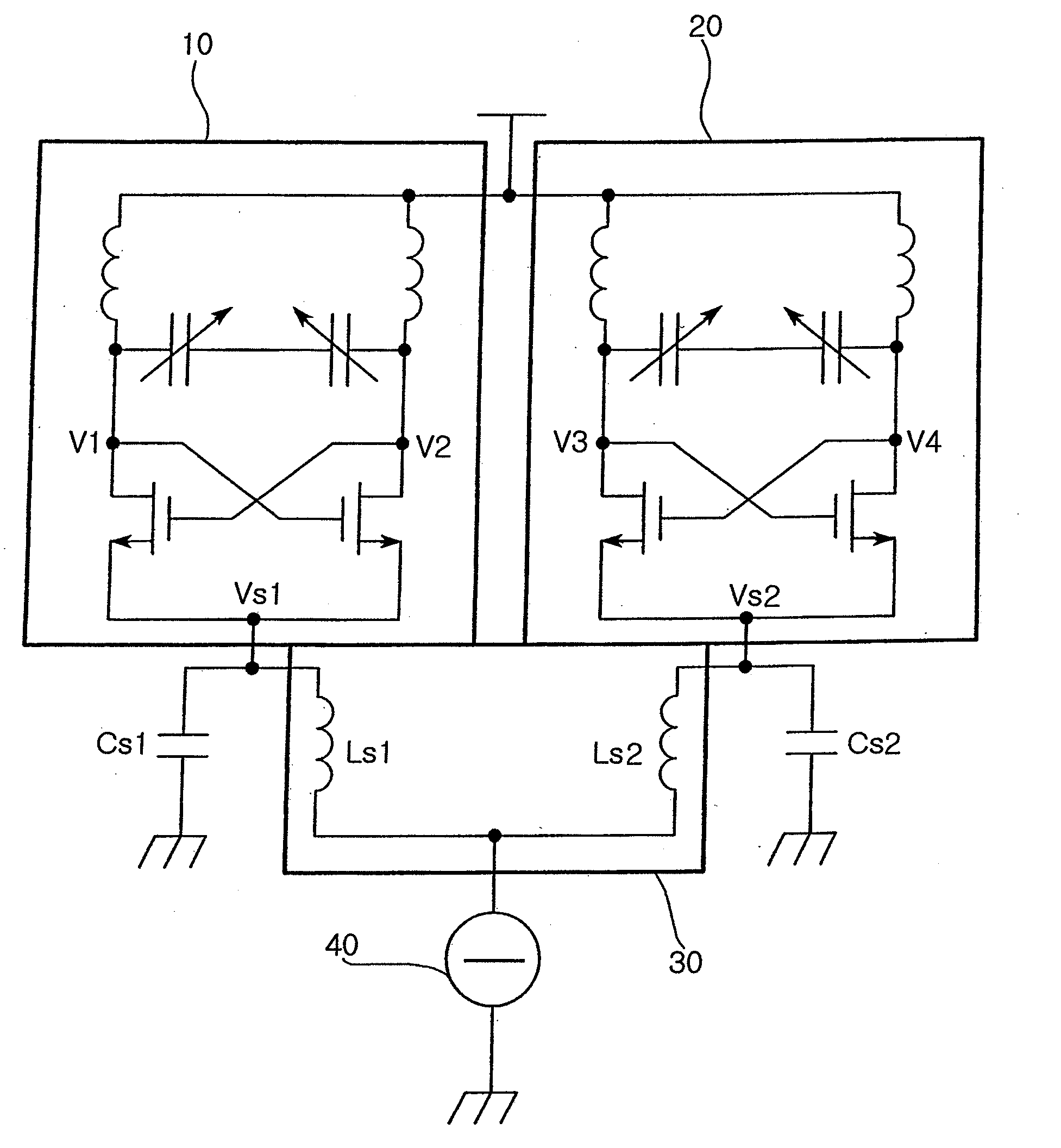
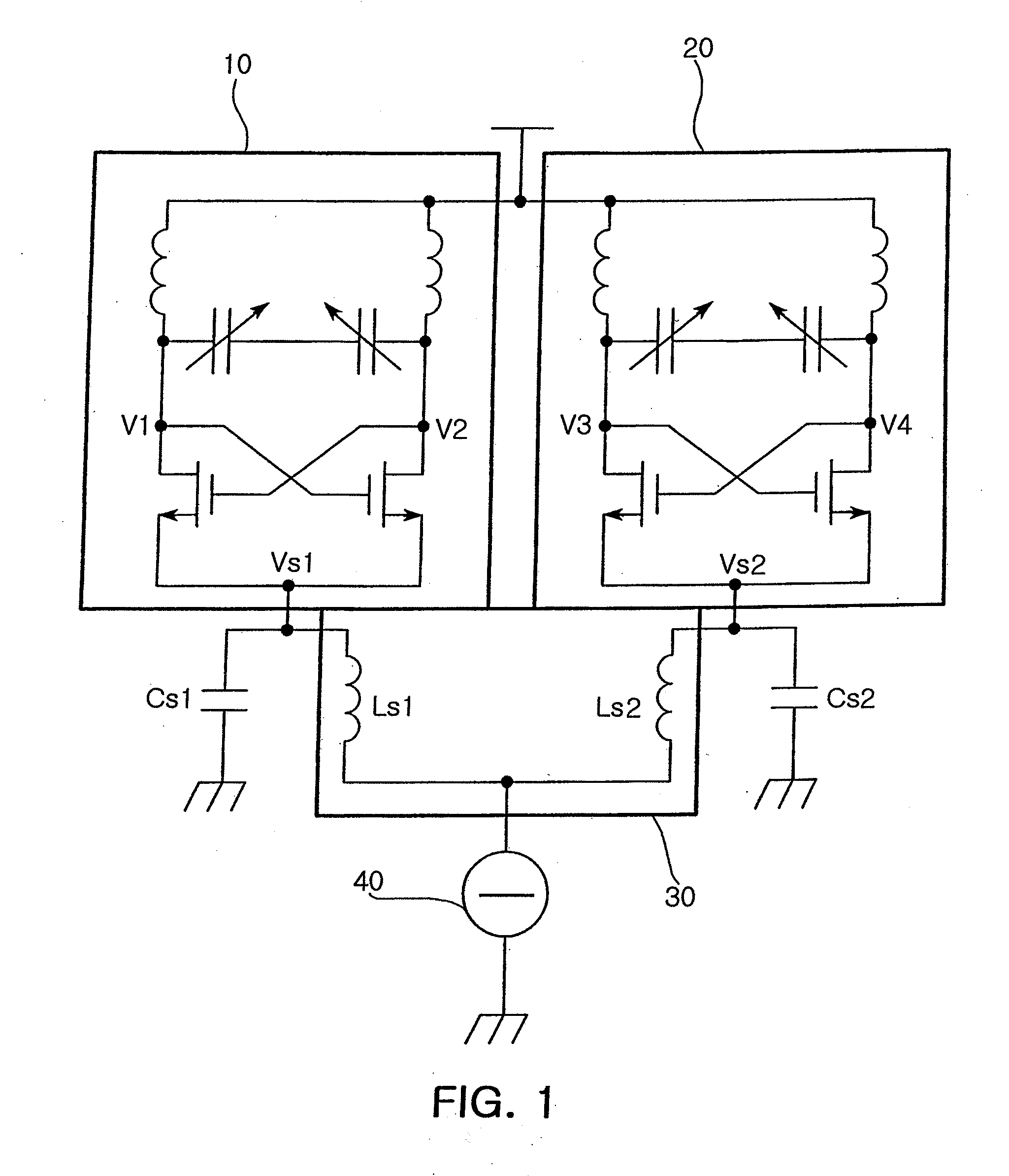
However, disadvantageously, the coils Ls1 and Ls2 need to be integrated inside an IC of the conventional quadrature voltage controlled oscillator.

Method used


Image

  • Quadrature voltage controlled oscillator
  • Quadrature voltage controlled oscillator
  • Quadrature voltage controlled oscillator

Examples


Embodiment Construction

[0037] Preferred embodiments of the present invention will now be described in detail with reference to the accompanying drawings, in which the same reference numerals are used throughout the different drawings to designate the same or similar components.

[0038]FIG. 2 is a circuit diagram illustrating a quadrature voltage controlled oscillator of the invention.

[0039] Referring to FIG.2, the quadrature voltage controlled oscillator of the invention includes a first oscillator 100, a second oscillator 200, a first current source 300, a second current source 400 and a differential load 500.

[0040] The first oscillator 100 includes a first resonant circuit 110 for generating a preset first resonant frequency and a pair of first cross-coupled transistors M11 and M12 for supplying energy to the first resonant frequency to generate first and second signals V1 and V2 having a phase difference of 180 degree.

[0041] The second oscillator 200 includes a second resonant circuit 210 for generat...


PUM


Abstract

In a quadrature voltage controlled oscillator, a first oscillator includes a first resonant circuit for generating a preset first resonant frequency and a first pair of cross-coupled transistors for supplying energy to the first resonant frequency to generate first and second signals having a phase difference of 180°. A second oscillator includes a second resonant circuit for generating a preset second resonant frequency and a second pair of cross-coupled transistors for generating third and fourth signals for supplying energy to the second resonant frequency having a phase difference of 180°. A first current source is connected between a first common node of the first cross-coupled transistor pair and a ground. A second current source is connected between a second common node of the second cross-coupled transistor pair and the ground. A differential load is connected between a third common node of the first and second current sources and the ground.

Description

CLAIM OF PRIORITY [0001] This application claims the benefit of Korean Patent Application No. 2005-86519 filed on Sep. 15, 2005 in the Korean Intellectual Property Office, the disclosure of which is incorporated herein by reference. BACKGROUND OF THE INVENTION [0002] 1. Field of the Invention [0003] The present invention relates to a quadrature voltage controlled oscillator employed in an RF transceiver which performs quadrature modulation / demodulation. More particularly, the present invention relates to a quadrature voltage controlled oscillator which has a common node configured as an inductor to differentiate a quadrature signal without using an active device, thereby achieving improved phase noise properties and reduced power consumption. [0004] 2. Description of the Related Art [0005] A demand for wireless communications has risen worldwide over the recent years. But a limited available frequency is driving up licensing costs for a specific frequency. Accordingly, companies and...

Claims


Application Information

Patent Timeline
IPC IPC(8): H04B1/40H04B1/06
CPCH03B27/00H03B2200/0078H03B5/1228H03B5/1215H03B5/1243H03B25/00H03B5/08
Inventor OH, SEUNG MINBAEK, WON JIN
Owner SAMSUNG ELECTRO MECHANICS CO LTD
Learn More