Electronic endoscope system

Inactive Publication Date: 2007-04-05
OLYMPUS CORP
View PDF6 Cites 62 Cited by
  • Summary
  • Abstract
  • Description
  • Claims
  • Application Information

AI Technical Summary

Benefits of technology

[0019] For solving the abovementioned issues, and achieving the object, according to the p

Problems solved by technology

Therefore, the washing of the electronic endoscope is not easy.
Furthermore, the coil is not preferable as the coil is a cause of generation of an electromagnetic noise.
Thus, due to an antenna for transceiving (transmitting and receiving) the image signal and the control signal by the electric waves, the scope section becomes a large scale, and it becomes difficult to have a structure which facilitates washing.
Furthermore, in addition to being weak against a noise generated by a medical e

Method used


Image

  • Electronic endoscope system
  • Electronic endoscope system
  • Electronic endoscope system

Examples


first embodiment

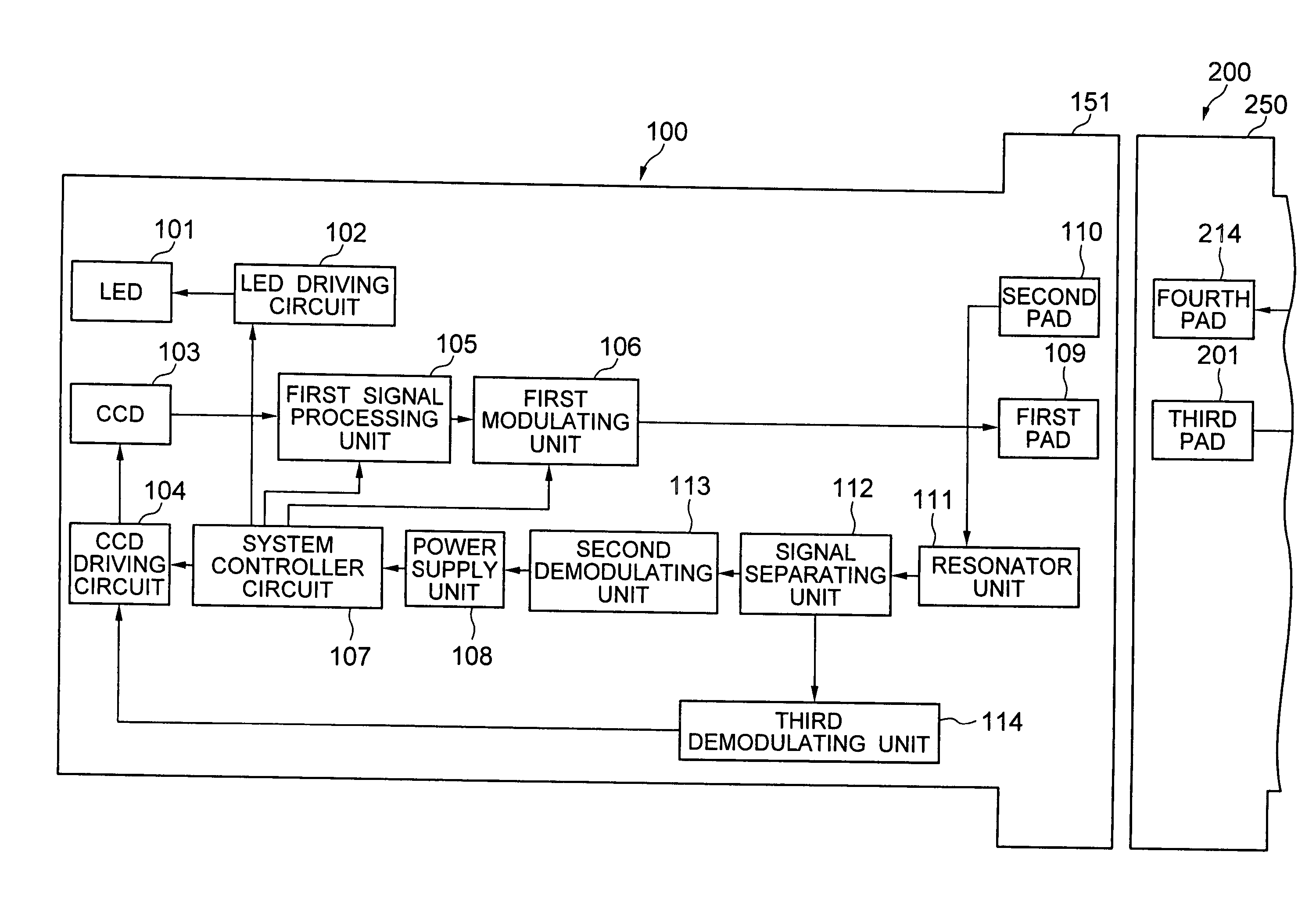
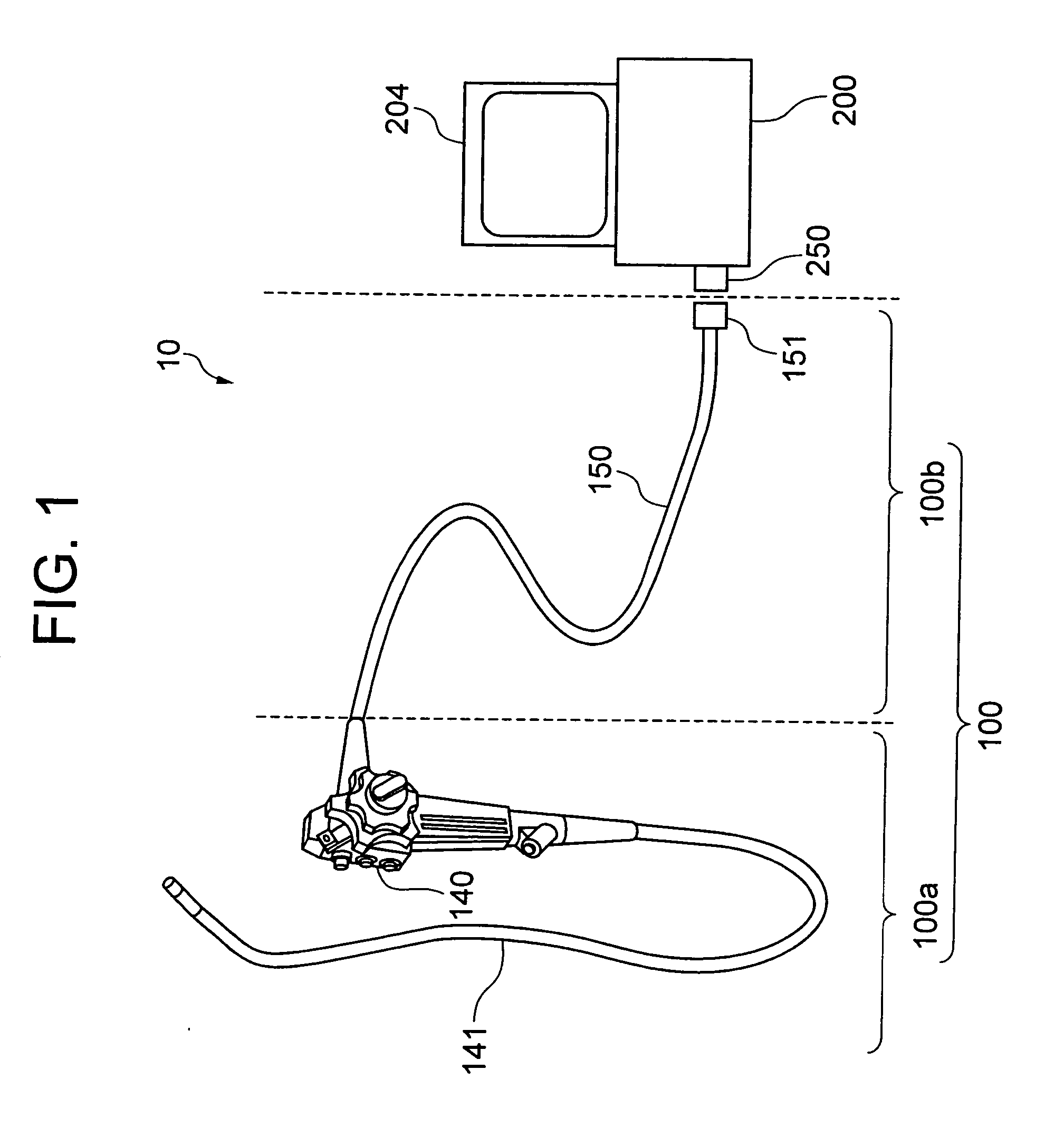
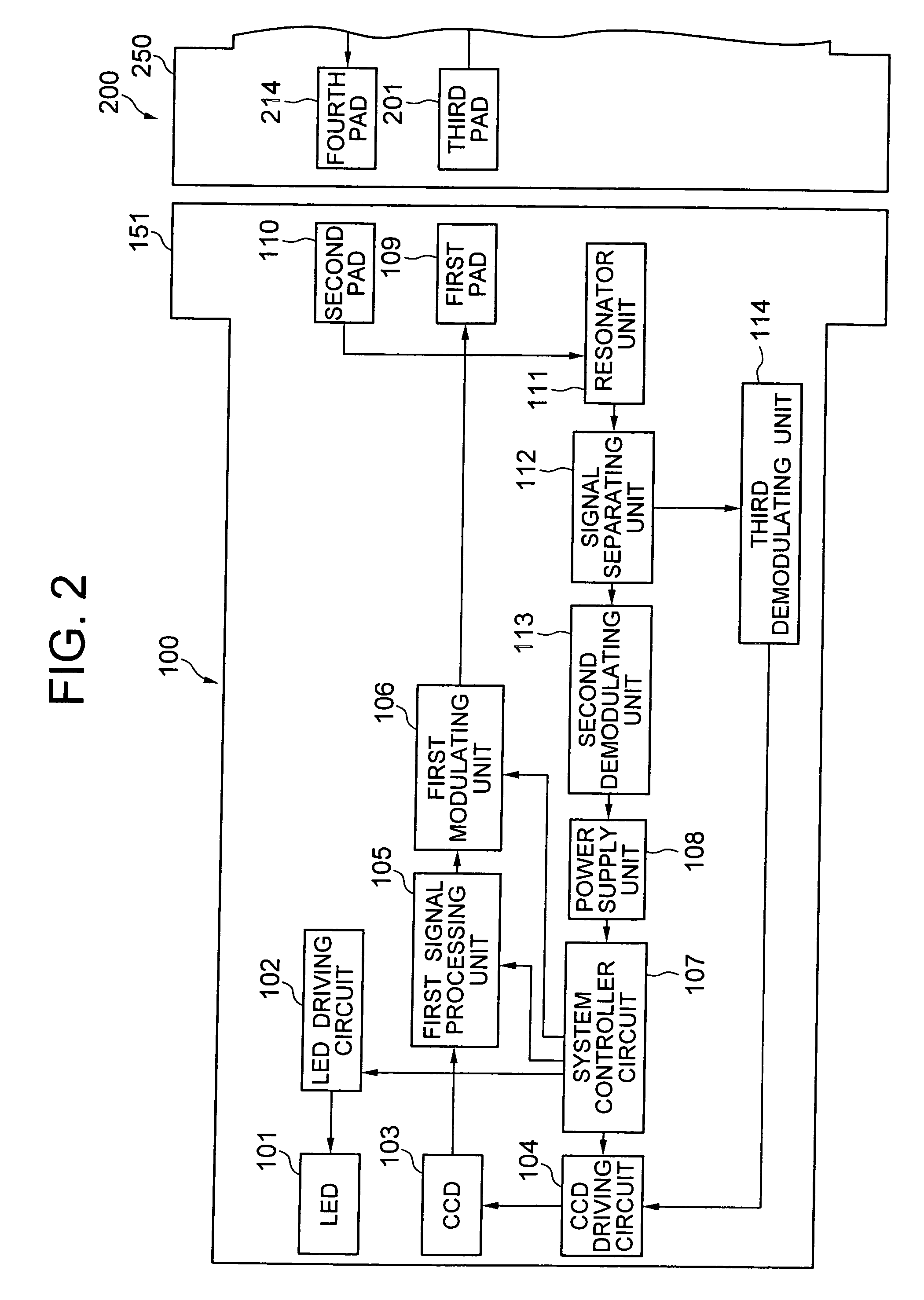
[0041]FIG. 1 is a diagram showing a schematic structure of an electronic endoscope system 10 according to a first embodiment of the present invention. The electronic endoscope system 10 includes an electronic endoscope 100 and an in vitro apparatus 200. The electronic endoscope 100 includes a scope section 100a and a connecting cord section 100b. Moreover, the in vitro apparatus 200 includes a power supply unit, a video processor (not shown in the diagram) which performs processing of an image signal from the electronic endoscope 100, and a display unit 204 which performs a monitor display of the image signal from the video processor. The scope section 100a corresponds to the in vivo apparatus.

[0042] The scope section 100a is mainly divided into an operating section 140 and an inserting section 141. The inserting section 141 includes a long and slender member having a flexibility, which can be inserted into a body cavity of a patient. A user (not shown in the diagram) can perform v...

second embodiment

[0094] Next, an electronic endoscope system 20 according to a second embodiment of the present invention will be described. FIG. 8 shows a schematic structure of the electronic endoscope system 20. Same reference numerals are used for components which are same as in the first embodiment, and the repeated description is omitted.

[0095] In the second embodiment, a connector 142 is formed at a portion of a scope section 300a, which is extended from the operating section 140. Moreover, a connector 154 is formed at an end portion of a connecting cord section 300b on a side of the scope section 300a.

[0096]FIG. 9 shows an enlarged structure of an area near the connectors 142 and 154. The structure of the connectors 142 and 154 is same as the structure of the connectors 151 and 250 respectively. Moreover, the first pad 109 and the third pad 201 are disposed adjacent facing each other so as to be coupled electrostatically. Similarly, the second pad 110 and the fourth pad 214 are disposed ad...

third embodiment

[0099] Next, an electronic endoscope system 30 according to a third embodiment of the present invention will be described. FIG. 10 shows a schematic structure of the electronic endoscope system 30. Same reference numerals are used for components which are same as in the first embodiment, and the repeated description is omitted.

[0100] In the third embodiment, similarly as in the first embodiment, the connector 151 is formed at the end portion of the universal cable 150. Moreover, the connector 250 is formed on the in vitro apparatus 200.

[0101] Furthermore, similarly as in the second embodiment, the connector 142 is formed at the portion of the scope section 300a, which is extended from the operating section 140. Moreover, the connector 154 is formed at the end portion of the connecting cord section 400b on the side of the scope section 300a.

[0102] Accordingly, in the third embodiment, it is possible to connect and separate easily each of the scope section 300a, the connecting cord...


PUM


Abstract

An electronic endoscope system includes a scope section, an in vitro apparatus which is installed outside a body, and a connecting cord section which connects the scope section and the in vitro apparatus. Each of the in vitro apparatus and the connecting cord section includes pads which are structured to be air tight and water tight, and connecting sections for bringing close upon facing each of the pads. Furthermore, for performing a communication of a signal between a pair of pads facing each other, the electronic endoscope system includes a first modulating unit which applies a voltage on one of the pads upon modulating the signal, and a demodulating unit which demodulates the signal from a change in an electric potential of the other pad.

Description

CROSS-REFERENCE TO RELATED APPLICATION [0001] The present application is based upon and claims the benefit of priority from the prior Japanese Patent Application No.2005-290047 filed on Oct. 3, 2005; the entire contents of which are incorporated herein by reference. BACKGROUND OF THE INVENTION [0002] 1. Field of the Invention [0003] The present invention relates to an electronic endoscope system which communicates in vivo information and an electric power between an apparatus which is introduced inside a body (hereinafter, “in vivo apparatus”) and an apparatus which is disposed outside the body (hereinafter, “in vitro apparatus”). [0004] 2. Description of the Related Art [0005] In a field of a living body, especially a living body of human (hereinafter, “body”), to be examined, particularly in vivo examination, and treatment, in vivo information is communicated outside the body by using an electronic endoscope. Moreover, an electric power etc. has been transmitted to the electronic ...

Claims


Application Information

Patent Timeline
IPC IPC(8): A61B1/00A61B1/04
CPCA61B1/00124A61B1/04G02B23/24
Inventor SHIMIZU, HATSUONAKAMURA, MIKIO
Owner OLYMPUS CORP
Why Eureka
Try Eureka