Implantable medical device

Inactive Publication Date: 2007-04-05
ANGIODYNAMICS INC
View PDF39 Cites 215 Cited by
  • Summary
  • Abstract
  • Description
  • Claims
  • Application Information

AI Technical Summary

Benefits of technology

[0015] It is a further object and advantage of the present invention to provide a non-invasive guidance system that can be incorporated into existing designs of the same sort of medical devices.
[0016] It is an additional object and advantage of the present invention to provide an implantable medical device for vascular access that may be used for high pressure fluid injections, and is distinctly identifiable as such.
[0017] It is another object and advantage of the present invention to provide a vascular access medical device that verifies proper access of the device.
[0018] It is another object and advantage of the present invention to provide a vascular access medical device that provides a visual indication of device malfunction.
[0019] Other objects and advantages of the present invention will in part be obvious and in part appear hereinafter.
[0020] In accordance with the foregoing objects and advantages, one aspect of the present invention provi

Problems solved by technology

Shrinking the size of these systems also requires shrinking the size of the vascular access port injection site or “needle target”.
As ports become smaller and smaller, or are located deeper in the tissue, it becomes more and more difficult to locate the proper insertion site or “needle target” required to infuse the desired medications through the tissue into the port reservoir.
This often results in unnecessary and repetitive insertions of the needle into the patient before the correct site is located allowing the needle to enter the port reservoir.
It is also difficult for the health care provider to know when the correct site has been accessed, as this is not an image-guided procedure.
CT without contrast media allows imaging of bones (similar to X-ray), but will not provide adequate imaging of soft tissue structures, such as tumors, organs and vasculature.
If the injection pres

Method used


Image

  • Implantable medical device
  • Implantable medical device
  • Implantable medical device

Examples


first embodiment

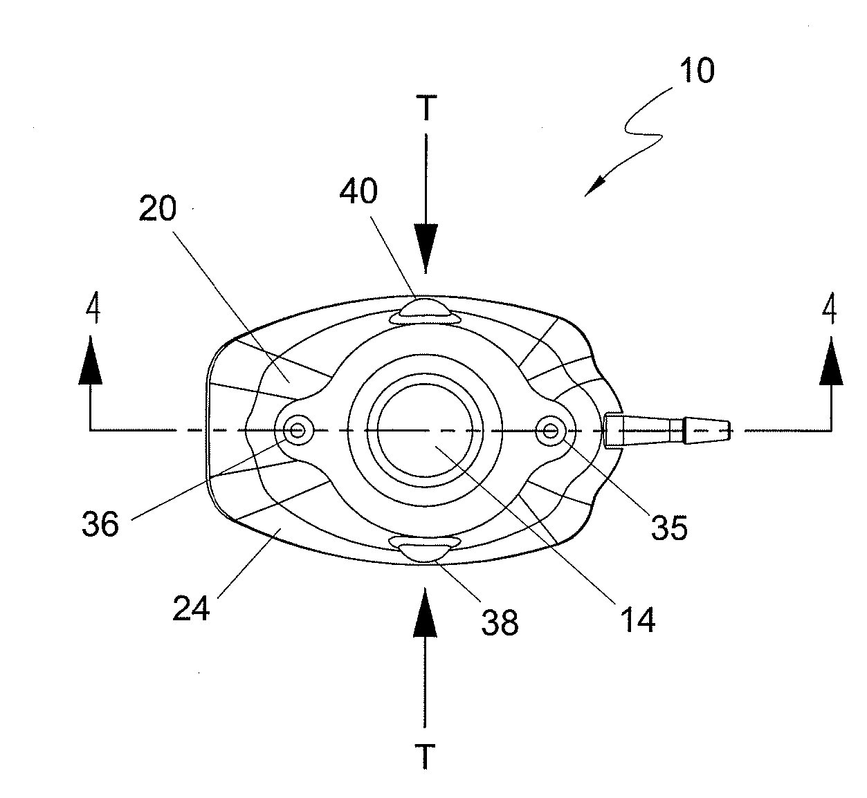
[0055] In the first embodiment, and in fact in each of the embodiments of the present invention, port 10 includes a guidance system that non-invasively defines the location of septum 14 for purposes of providing a well-defined target for the medical personnel who need to insert a needle through the septum. In each of the embodiments the guidance system comprises at least one light emitting element that is incorporated into port 10 and is adapted to be viewable through the skin of the patient in which the port is subcutaneously implanted. By viewing the light that defines the septum location, the medical personnel will be able to accurately insert the needle through the septum without “trial and error.” The light can also be used to identify the port type, such as a CT-injectable port.

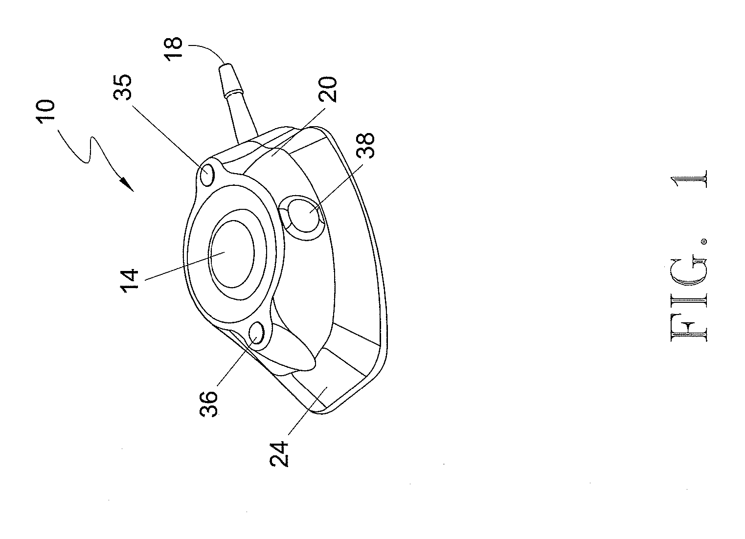
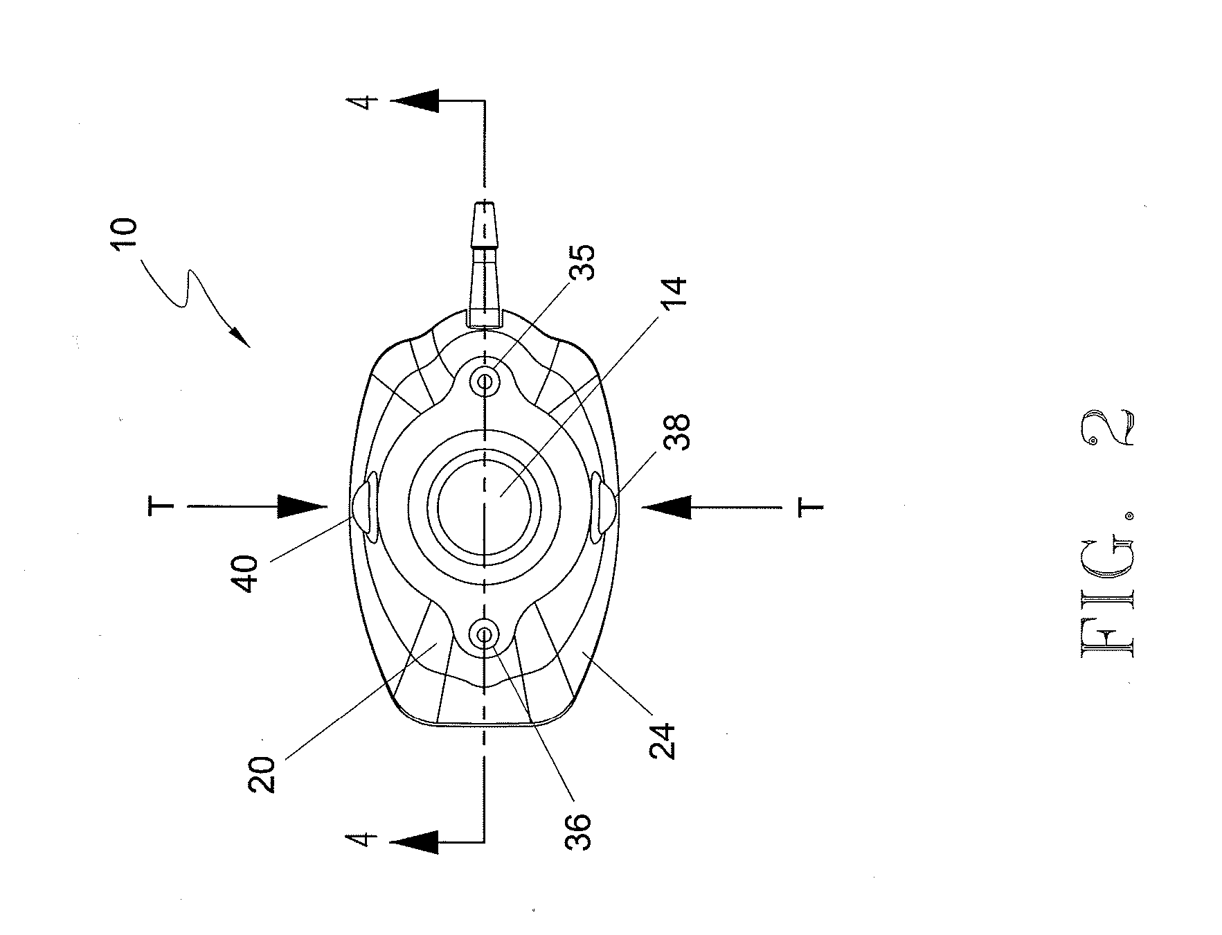
[0056] With reference to FIGS. 1-8, a first embodiment of port 10 is illustrated. In this embodiment, shown in an assembled state in FIGS. 1-5, port 10 comprises an upper housing 20 having a opening 22 ...

third embodiment

[0088] With reference to FIGS. 14-20, a vascular access port 300 constituting the present invention is illustrated. Port 300 generally comprises an outer jacket 302 comprised of a flexible material, a main housing 304 situated within and including a body shape that contours outer jacket 302, a reservoir 306 formed in main housing 304, a pair of batteries 308, 310 that are securely positioned within main housing 304, an LED circuit 312 electrically coupled to batteries 308, 310, and that includes an opening 314 formed therethrough which is positioned concentrically around reservoir 306, a septum 316 that extends through opening 314 and in sealing relation to the open top of reservoir 306, and a cover 318 that is fixedly secured to main housing 304 and in covering relation to the other components of port 300. An exit lumen 320 extends outwardly from main housing 304, through outer jacket 302, and in fluid communication with reservoir 306.

[0089] With reference to FIG. 18A and 18B, batt...


PUM


Abstract

A medical device suitable for subcutaneous implantation, generally including a housing having a reservoir, a septum positioned within and supported by the housing, at least one light emitting element placed in position defining relation to the septum, and a pressure actuated, light activating circuitry associated with the at least one light emitting element. The light element(s) may be positioned, for instance, in at least partially surrounding relation around the septum, embedded within or below a translucent housing that supports the septum, positioned within the reservoir and adapted to emit its light through a translucent septum, or positioned on the exterior of the supporting housing. The medical device can be adapted to receive high pressure fluid injections and if so adapted, will include a light emitting element that will provide a visual indication this capacity.

Description

PRIORITY CLAIM [0001] The present application claims priority to U.S. Provisional Application Ser. No. 60 / 722,800, filed Sep. 30, 2005, the entirety of which is hereby incorporated by reference.BACKGROUND OF THE INVENTION [0002] 1. Field of Invention [0003] The present invention relates generally to implantable medical devices, and more particularly to vascular access devices, such as ports, and methods associated with such devices. [0004] 2. Description of the Art [0005] As known in the art, vascular access systems are used to provide recurring access to the body of a patient when performing various therapeutic or diagnostic procedures. The vascular access system typically contains a vascular access port and an elongated, pliable catheter that is coupled to the port. The port is implanted in shallow tissue areas in the body of patient, such as subcutaneously under the skin. The entire device is located subcutaneously to enhance a patient's quality of life. Because the vascular acce...

Claims


Application Information

Patent Timeline
IPC IPC(8): A61M5/00
CPCA61M39/0208A61M2039/0054A61M2039/0238A61M2039/0244A61M2205/587A61M2205/8206A61M2039/0036A61M2205/0205A61M2205/0233
Inventor WORTLEY, RONALDKING, ERICDI PALMA, GIORGIO
Owner ANGIODYNAMICS INC
Why Eureka
Try Eureka