Capacitive load driving circuit and method, liquid droplet ejection device, and piezoelectric speaker driving device

Inactive Publication Date: 2007-04-12
FUJIFILM BUSINESS INNOVATION CORP
View PDF6 Cites 58 Cited by
  • Summary
  • Abstract
  • Description
  • Claims
  • Application Information

AI Technical Summary

Benefits of technology

[0013] The present invention has been made in view of the above circumstances, and provides a capacitive load driving circuit and method, a liquid drople

Problems solved by technology

Therefore, there is the problem that, if a large number of nozzles are driven simultaneously, a large amount of heat is generated and the energy efficiency is poor (30 to 40%).
Second, if there are many nozzles which are driven simultaneously, the impedance of the load decreases and the waveform becomes weak (dull).
As a result, the jetting characteristics of the head are affected

Method used


Image

  • Capacitive load driving circuit and method, liquid droplet ejection device, and piezoelectric speaker driving device
  • Capacitive load driving circuit and method, liquid droplet ejection device, and piezoelectric speaker driving device
  • Capacitive load driving circuit and method, liquid droplet ejection device, and piezoelectric speaker driving device

Examples


first embodiment

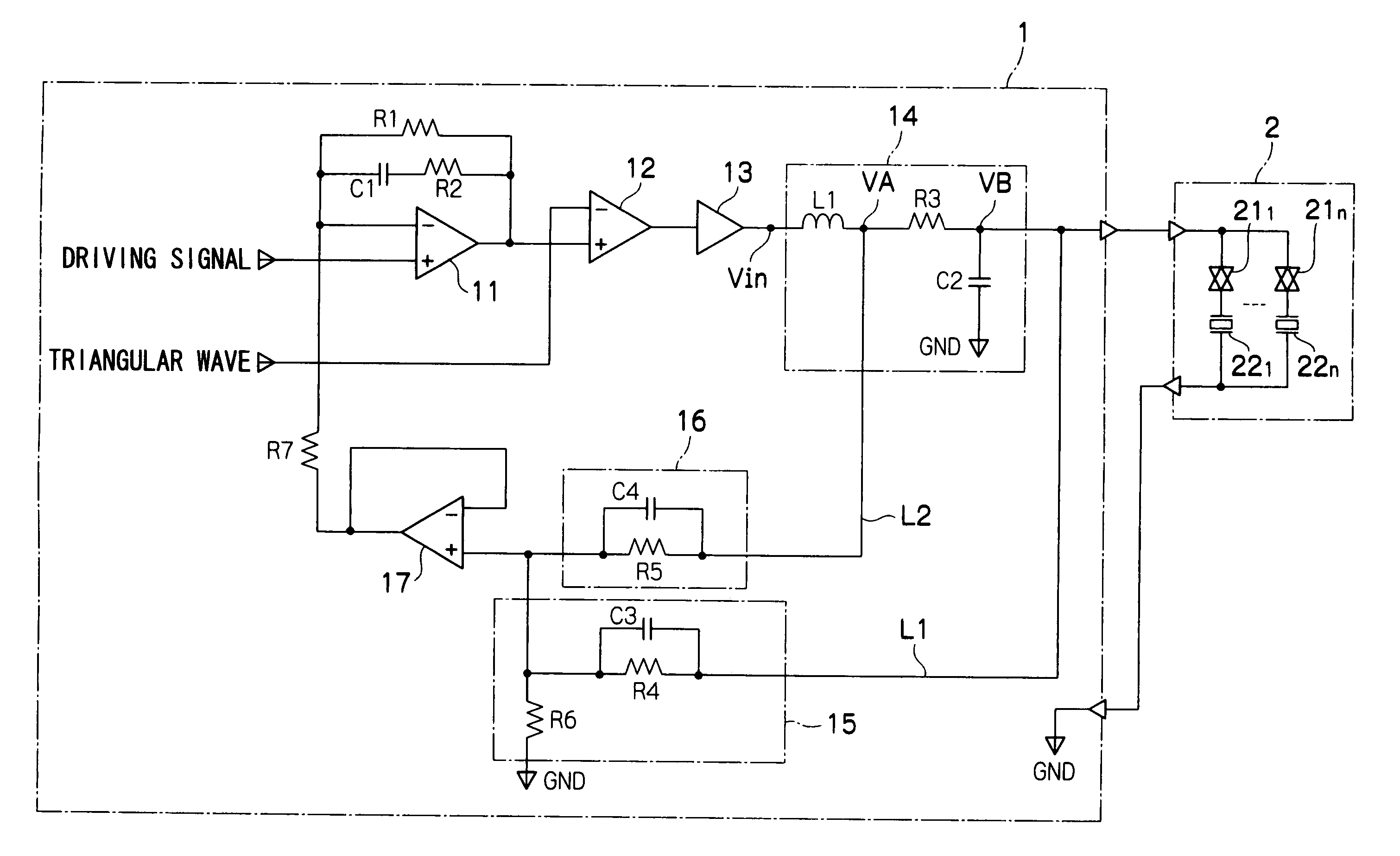
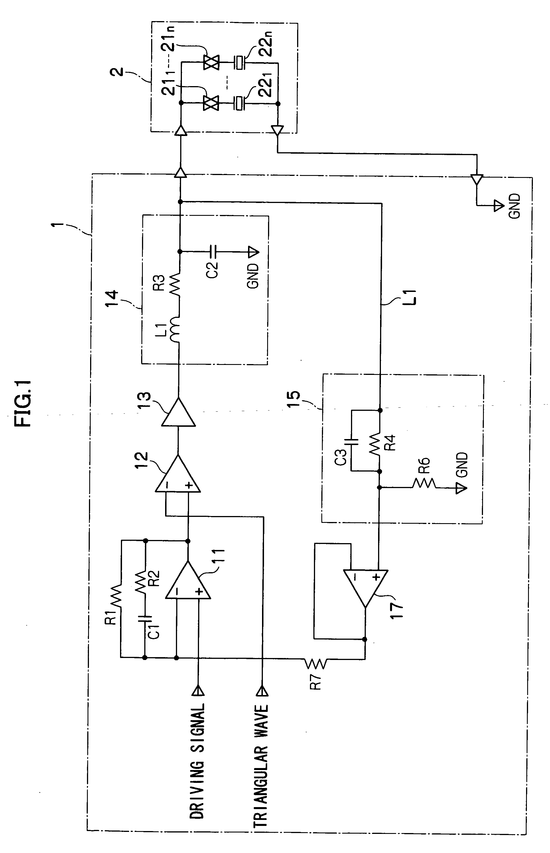
[0030]FIG. 1 is a diagram showing the circuit structure of a liquid droplet ejection device relating to a first embodiment. The liquid droplet ejection device has a driving circuit board 1 and a head 2. An operational amplifier 11, a comparator 12, a digital voltage amplifier 13, and a first filter 14 are provided at the driving circuit board 1.

(Overall Structure 1)

[0031] The head 2 has n (where n is a natural number) transfer gates 211 through 21n, and n piezoelectric actuators 221 through 22n which are connected in series to the transfer gates 211 through 21n, respectively.

[0032] An analog driving signal is inputted to the non-inverting input terminal of the operational amplifier 11. The output terminal of the operational amplifier 11 is connected to the non-inverting input terminal of the comparator 12 which structures a pulse width modulator. Further, the output terminal of the operational amplifier 11 is connected to the inverting input terminal of the operational amplifier...

second embodiment

[0109] A second embodiment of the present invention will be described next. Circuits which are the same as those of the first embodiment are denoted by the same reference numerals, and repeat, detailed description of circuits is omitted.

[0110]FIG. 5 is a diagram showing the circuit structure of a liquid droplet ejection device relating to the second embodiment. The liquid droplet ejection device relating to the second embodiment is a device in which a second feedback circuit 16 is added to the structure shown in FIG. 1.

[0111] The second feedback circuit 16 is a parallel circuit of a capacitor C4 and a resistor R5. One end of the resistor R5 is connected to the output side of the inductor L1 of the first filter 14 (the connecting portion of the inductor L1 and the resistor R3). The other end of the resistor R5 is connected to the non-inverting input terminal of the operational amplifier 17.

[0112] Here, given that the output voltage of the digital voltage amplifier 13 is Vin, the o...

third embodiment

[0117] A third embodiment of the present invention will be described next. Circuits which are the same as those of the above-described embodiments are denoted by the same reference numerals, and repeat, detailed description of circuits is omitted.

[0118]FIG. 6 is a diagram showing the circuit structure of a liquid droplet ejection device relating to the third embodiment. The liquid droplet ejection device relating to the third embodiment is a device in which the second feedback circuit 16 and a second filter 18 are added to the structure shown in FIG. 1.

[0119] The structure of the second feedback circuit 16 is similar to that of the second embodiment (FIG. 5). However, one end of the resistor R5 is connected to the output terminal of the digital voltage amplifier 13 via the second filter 18. The other end of the resistor R5 is connected to the non-inverting input terminal of the operational amplifier 17.

[0120] The second filter 18 is structured by a resistor R9 and a capacitor C6....


PUM


Abstract

There is provided a capacitive load driving circuit which applies a driving signal to a capacitive load. The driving circuit includes: an operational amplifier outputting a difference signal between signals from an inverting input terminal and a non-inverting input terminal, and setting a loop gain; a pulse width modulator pulse-width-modulating the difference signal outputted by the operational amplifier, and outputting resultant digital signal; a digital voltage amplifier amplifying a voltage of the digital signal; a first filter smoothing a digital signal from the digital voltage amplifier, and supplying a smoothed signal to the capacitive load as the driving signal; an impedance converting circuit converting an impedance of an output signal of the first filter; and a first feedback circuit feeding-back the driving signal, which is outputted from the first filter, to the inverting input terminal of the operational amplifier via the impedance converting circuit.

Description

CROSS-REFERENCE TO RELATED APPLICATION [0001] This application claims priority under 35 USC 119 from Japanese Patent Application No. 2005-278806, the disclosure of which is incorporated by reference herein. BACKGROUND OF THE INVENTION [0002] 1. Field of the Invention [0003] The present invention relates to a capacitive load driving circuit and method, a liquid droplet ejection device, and a piezoelectric speaker driving device, and in particular, to a capacitive load driving circuit and method, a liquid droplet ejection device, and a piezoelectric speaker driving device which stably operate a capacitive load. [0004] 2. Description of the Related Art [0005] A driving circuit of an inkjet head outputs an analog driving signal to a piezoelectric element for ejecting an ink droplet from a nozzle of the inkjet head, and thereby causes an ink droplet to be ejected from the nozzle which is provided so as to correspond to that piezoelectric element. A piezoelectric actuator is a capacitive ...

Claims


Application Information

Patent Timeline
IPC IPC(8): B41F3/42
CPCB41J2/04541B41J2/04581H04R3/00H04R17/00
Inventor ISHIZAKI, SUNAO
Owner FUJIFILM BUSINESS INNOVATION CORP
Why Eureka
Try Eureka