Electric fan

Inactive Publication Date: 2007-04-12
HON HAI PRECISION IND CO LTD
View PDF7 Cites 20 Cited by
  • Summary
  • Abstract
  • Description
  • Claims
  • Application Information

AI Technical Summary

Benefits of technology

[0006] According to a preferred embodiment of the present invention, an electric fan includes a frame having a central tube extending therefrom, a bearing received in the central tube, a stator mounted around the central tube, and a rotor being rotatably supported by the bearing received in the central tube. The frame defines an air inlet and an air outlet at two different sides thereof. The stator includes two poles and a tube arranged between the poles. Each pole includes a basewall and a sidewall extending from the basewall. Each sidewall includes an upper portion adjacent to the air inlet expanding radially along a direction from the air inlet to the air outle

Problems solved by technology

However, this way will increase the size of the cooling fan, which is disadvantageous in view of miniaturization requirement of electronic products.
However, the yokes of the stator core 62 are formed by stamping silicon-steel sheets, each of which has a flat configuration and a predetermined diameter; thus, the size and the shape of the stator core 62 are almost fixed and dif

Method used


Image

  • Electric fan
  • Electric fan
  • Electric fan

Examples


Example

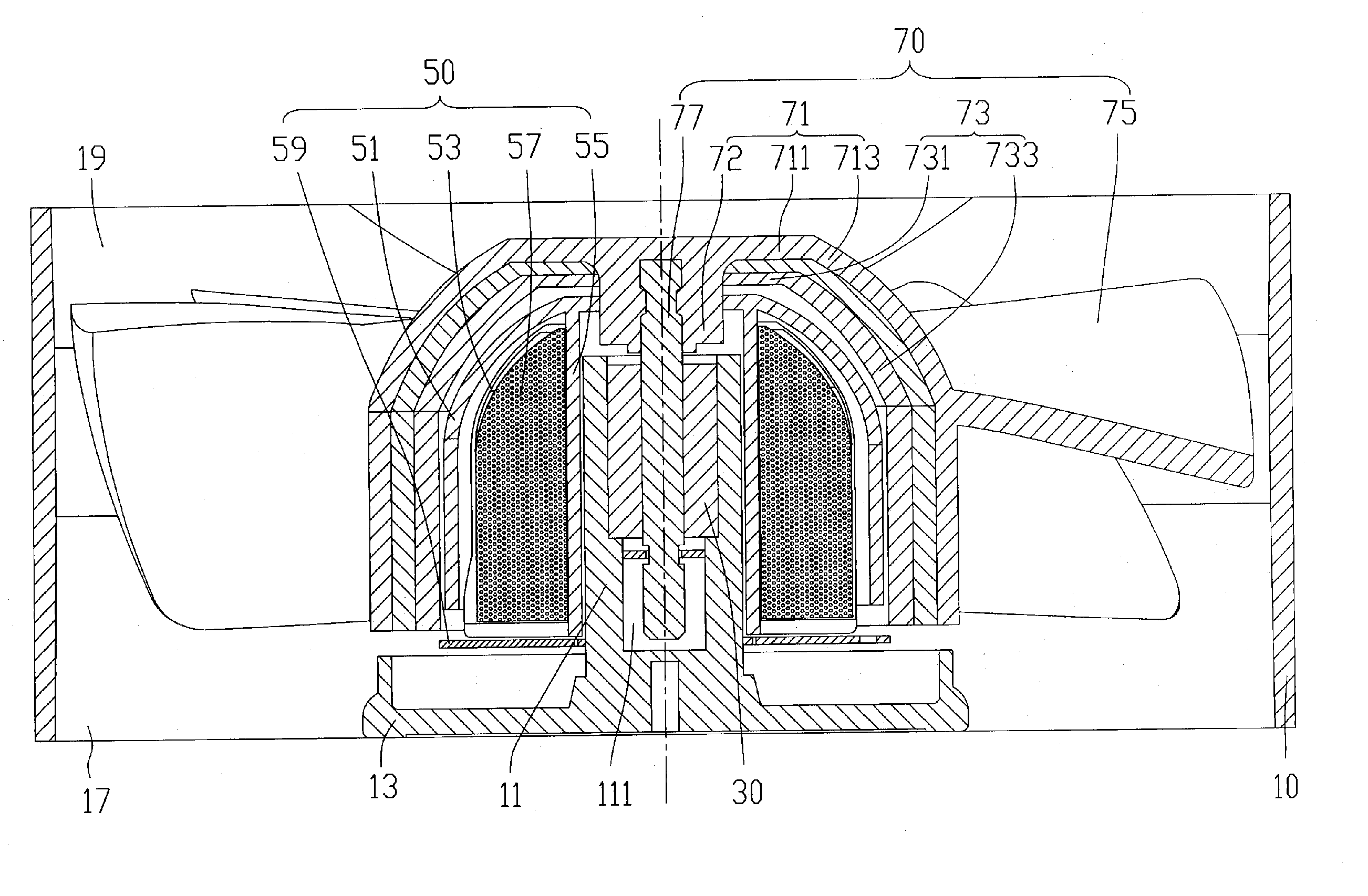
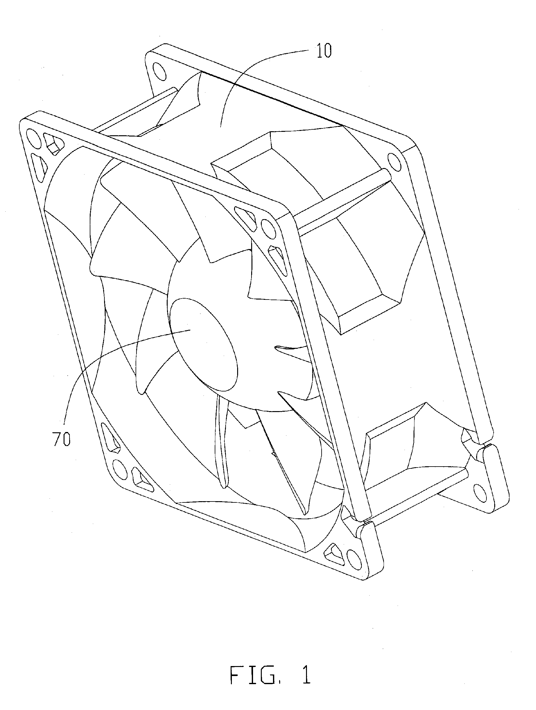
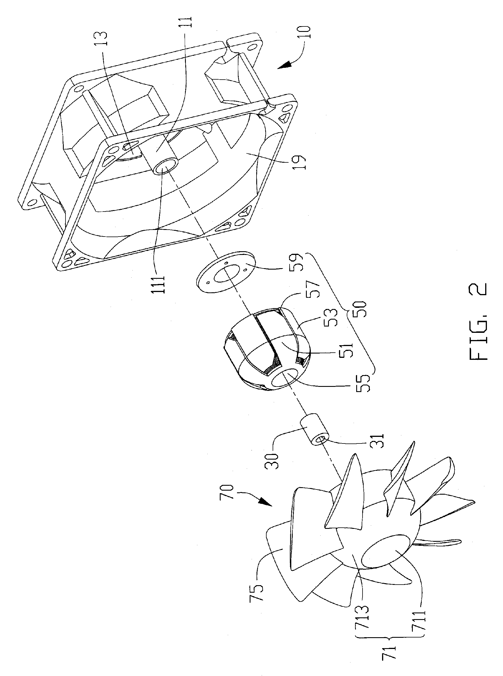
[0019] Referring to FIGS. 1 through 3, an electric fan according to a first embodiment of the present invention includes a rotor 70, a stator 50 in respective to which the rotor 70 is rotatable, a frame 10 receiving the rotor 70 and the stator 50 therein, and a bearing 30 mounted in the frame 10 for supporting the rotor 70 to rotate.

[0020] The frame 10 is square shaped. An air inlet 19 and air outlet 17 are defined at two opposite sides of the frame 10. An airflow generated by the fan flows from the air inlet 19 to the air outlet 17. The frame 10 includes a base 13 adjacent to the air outlet 17. A central tube 111 extends upwardly from a central portion of the base 13. The central tube 11 defines a central hole 111 receiving the bearing 30 therein. An axial hole 31 is defined in the bearing 30.

[0021] Referring to FIGS. 4 and 5, the stator 50 is mounted around the central tube 11. The stator 50 includes upper and lower poles 51, 53, a tube 55 interconnecting the upper and lower pol...

Example

[0026] Referring to FIGS. 8-9, it illustrates a third embodiment of a stator 50b of the electric fan. In this embodiment, the tube 55b and the upper pole 51b are formed separately and then assembled together. The basewalls 511b, 531b of the upper and lower poles 51b, 53b each forms a pair of latches 519b, 539b thereon. A pair of openings 551b is defined in each of the top and bottom ends 551b, 553b of the tube 55b corresponding to the latches 519b, 539b of the upper and lower poles 51b, 53b, respectively. During assembly each latch 519b, 539b of the poles 51b, 53b engages with a corresponding opening 555b of the tube 55b to securing the assembly of the stator 50b. Alternatively, the latches 519b, 539b can be formed on the tube 55b, and the basewalls 511b, 531b of the poles 51b, 53b can each define an opening 553b corresponding to each latch 519b, 539b of the tube 55b. Also the tube 55 (55a, 55b) and the poles 51, 53 (51a, 53a, 51b, 53b) can be assembled together in various manners, ...


PUM


Abstract

An electric fan includes a frame (10) having a central tube (11) extending therefrom, a bearing (30) received in the central tube, a stator (50) mounted around the central tube, and a rotor (70) being rotatably supported by the bearing received in the central tube. The frame defines an air inlet (19) and an air outlet (17) at two different sides thereof. The stator includes two poles (51, 53) and a tube (55) arranged between the poles. Each pole includes a basewall (511, 531) and a sidewall (513, 533) extending from the basewall. Each sidewall includes an upper portion adjacent to the air inlet expanding radially along a direction from the air inlet to the air outlet of the electric fan.

Description

FIELD OF THE INVENTION [0001] The present invention relates to an electric fan, and more particularly to a motor for an electric fan. DESCRIPTION OF RELATED ART [0002] With the continuing development of electronic technology, electronic packages such as CPUs (central processing units) are generating more and more heat that requires immediate dissipation. Electric cooling fans are commonly used in combination with heat sinks for cooling the CPUs. [0003] Referring to FIG. 10, a conventional electric cooling fan includes a stator 6, a rotor 8 rotatable with respect to the stator 6, and a fan housing 2 receiving the rotor 8 and stator 6 therein. The stator 6 is approximately cylinder-shaped and typically includes a stator core 62 and stator coils 64 wound around the stator core 62. The stator core 62 consists of layered yokes. Each yoke includes a ring shaped center portion and a plurality of pole members extending outwardly from the center portion for winding the coils thereon. To avoi...

Claims


Application Information

Patent Timeline
IPC IPC(8): H02K7/00H02K21/12
CPCF04D29/329H02K1/145H02K7/14F04D25/064F04D25/0646
Inventor YANG, CHIH-HAOTUNG, CHAO-NIENYU, FONG-TANWANG, CHIUNG-MEIHOU, CHUEN-SHULIU, TAY-JIAN
Owner HON HAI PRECISION IND CO LTD
Why Eureka
Try Eureka