Remote control system, and display device and electronic device using the remote control system

a remote control and display device technology, applied in the field of remote control system, can solve the problems of troublesome key pressing, complicated key operation, complicated signal processing, etc., and achieve the effect of simple remote operation and simple procedur

Inactive Publication Date: 2007-04-12
SHARP KK
View PDF13 Cites 119 Cited by
  • Summary
  • Abstract
  • Description
  • Claims
  • Application Information

AI Technical Summary

Benefits of technology

[0106] Furthermore, an electronic device according to the present invention may be an electronic device that can control a camera device and includes a remote operation device that emits as output various light signals from a light-emission unit, wherein a light-reception detection unit that receives the light signals and detects a change in a light reception amount, and an orientation of the camera device is moved in a lateral direction or a vertical direction based on a change in a light reception amount detected by the light-reception detection unit by swinging the remote operation device in the lateral or the vertical direction. Thus, since the orientation of the camera device can be changed by changing the orientation of the remote operation device, it is possible to operate the camera device more intuitively as compared with, for example, a case where the camera device is operated by pressing a cross-shaped key disposed on the remote operation device. This technique is applicable not only to

Problems solved by technology

The remote operation body of this remote coordinate indicating device disclosed in Patent Document 1 is provided with a total of five light-emitting element systems, and configured such that the light-emitting elements simultaneously emit light in groups of two or more, making the signal processing complicated.
On the other hand, with the evolution of various electronic devices, a very large number of keys are arranged on the remote control transmitter, making it troublesome to find a key to be pressed.
Moreover, the key operation has become complicated, and it has become necessary to press multiple keys.
In the case of selecting the necessary ones from among a huge number of recorded programs or TV channels, it has been troublesome to make a selection from their listings, and the search operation has been complicated.
As described above, the conventional remote control operation is complicated, and has reached its limitations.
However, when this is applied to a television receiver (hereinafter, occasionally referred to as “TV”) in a living room, the operation space for a mouse that is placed a

Method used


Image

  • Remote control system, and display device and electronic device using the remote control system
  • Remote control system, and display device and electronic device using the remote control system
  • Remote control system, and display device and electronic device using the remote control system

Examples


embodiment 1

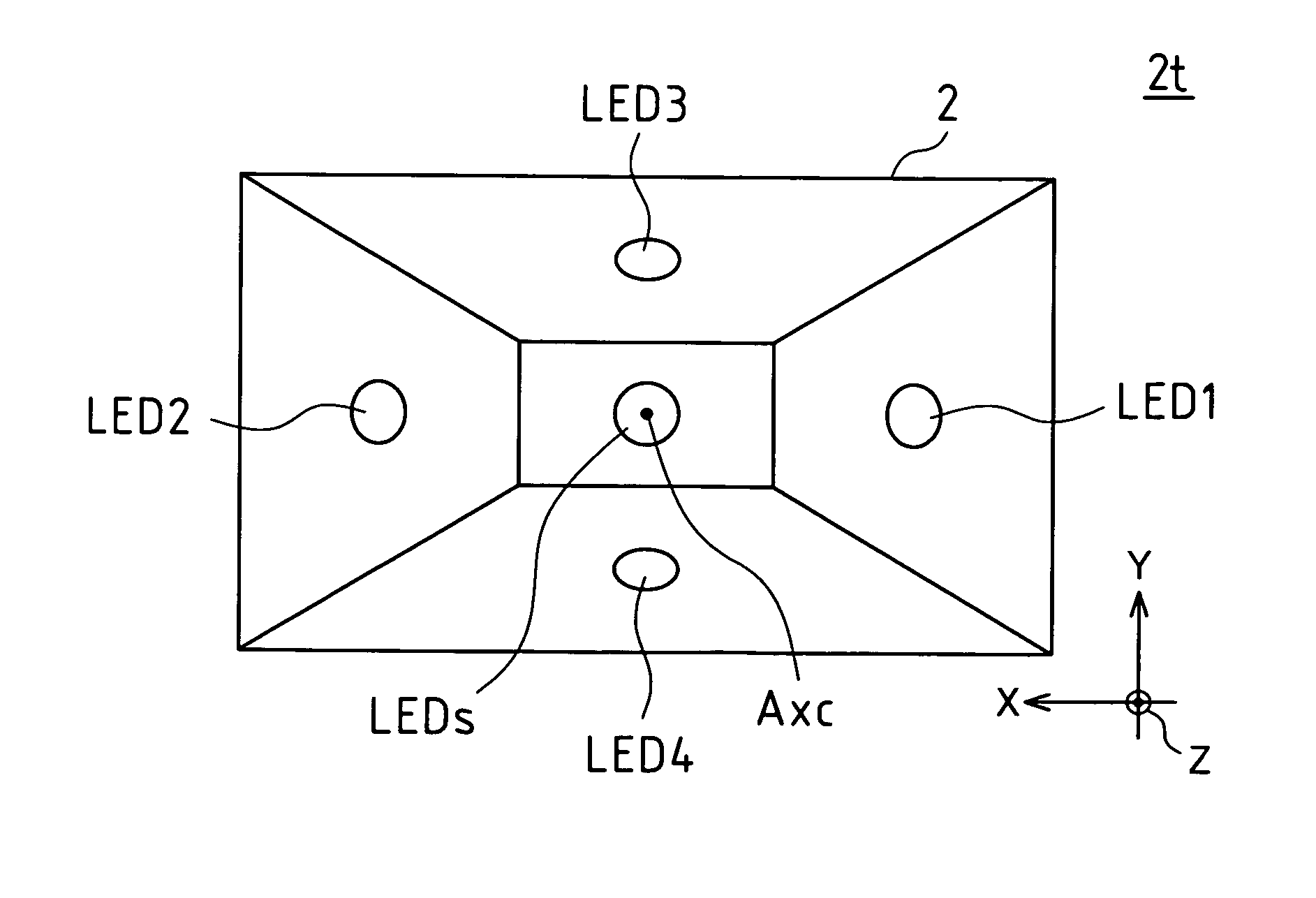
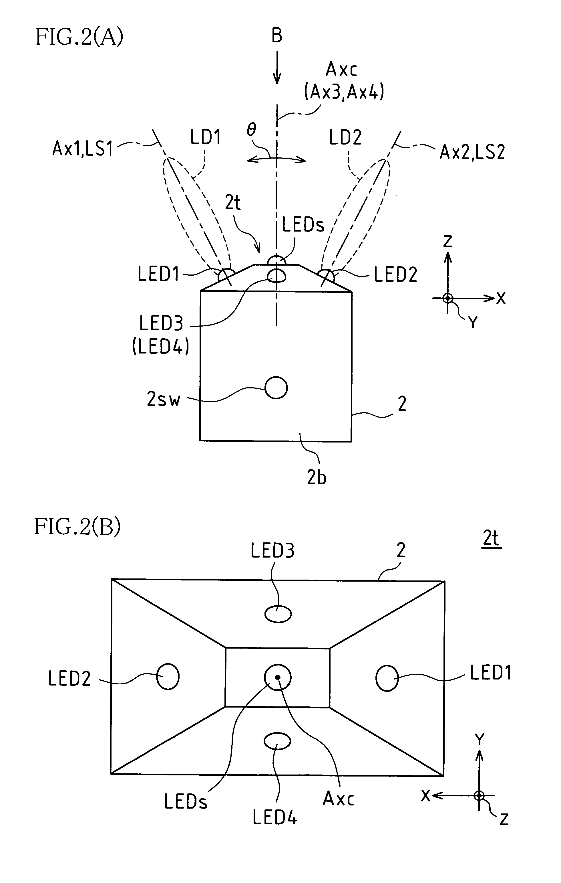
[0195] FIGS. 2(A) and 2(B) are explanatory diagrams schematically showing an external view of the remote control transmitter according to Embodiment 1 of the present invention. FIG. 2(A) is a plan view as viewed from vertically above during use, and FIG. 2(B) is a front view as viewed from the arrow B direction in FIG. 2(A).

[0196] A first light-emitting element LED1 (disposed on the right side in the front view) and a second light-emitting element LED2 (disposed on the left side in the front view) are arranged at a tip portion 2t of a transmitter 2 such that they are symmetrical about the intersecting point between a central axis Axc of the transmitter 2 and a first axis direction X (corresponding to a horizontal direction) of the tip portion 2t (a front portion of the transmitter 2 that is made opposite to a light-receiving unit 3p) of the transmitter 2.

[0197] The first light-emitting element LED1 and the second light-emitting element LED2 are disposed on inclined planes appropri...

embodiment 2

[0251] The detection of displacement and the state of display to the display screen in the remote control system 1 shown in Embodiment 1 are specifically described as Embodiment 2. To facilitate understanding, this embodiment is described for the case where the transmitter 2 is moved (displaced, swung) only in a horizontal direction (the first axis direction X). Therefore, no description is given for movement in a vertical direction (the second axis direction Y), but it is possible to similarly apply this embodiment. Detection of movement (detection of displacement, detection of swinging) in two-dimensional directions can be carried out by performing suitable combining processing based on the values (the amplitude ratios as an amplitude correlation, the logarithms of the amplitude ratios as an amplitude correlation) obtained for movement in both the horizontal direction and the vertical direction, and therefore its description is omitted.

[0252]FIG. 8 is a diagram showing a layout o...

embodiment 3

[0290] In this embodiment, the logarithm of the amplitude ratio shown in Embodiment 2 is linearly approximated to detect a displacement of the transmitter 2. That is, a linear approximation of the logarithm of the amplitude ratio is used as the amplitude correlation.

[0291]FIG. 14 is a graph showing a relationship between the swing angle and the logarithm of the amplitude ratio of the position detection output signals when linear approximation is applied to the logarithm of the amplitude ratio of the position detection output signals in a remote control system according to Embodiment 3 of the present invention.

[0292] The data in this embodiment is the same as that used in Embodiment 2, and the lateral axis denotes the swing angle θ (degrees), and the longitudinal axis denotes the logarithm of the amplitude ratio log (VL1 / VL2), as in FIG. 10. In a system 1 (receiver 3) according to this embodiment, the logarithm of the amplitude ratio is regarded as an approximating straight line AL...


PUM


Abstract

One embodiment of a remote control system according to the invention includes: a remote control transmitter including a light-emitting element control unit that emits light-emitting element that emit position detection light signals; a remote control receiver including a light-reception signal processing unit that detects position detection reception signals from the position detection light signals, an output detection unit that performs waveform conversion on the position detection reception signals to obtain output signals as position detection output signals, and an arithmetic processing unit that calculates a displacement of the remote control transmitter in a first axis direction and a second axis direction based on an amplitude correlation of output signals; and a cursor control unit that controls the position of the cursor based on the displacement of the remote control transmitter in the first axis direction and the displacement of the remote control transmitter in the second axis direction.

Description

BACKGROUND OF THE INVENTION [0001] This application claims priority under 35 U.S.C. § 119(A) on Patent Application No. 2005-295132 filed in Japan on Oct. 7, 2005, and Patent Application No. 2005-327610 filed in Japan on Nov. 11, 2005, the entire contents of which are hereby incorporated by reference. [0002] The present invention relates to a remote control system that controls the position of a cursor displayed on a display screen from a distant location, and also to a display device that controls a cursor that is displayed on a display screen by such a remote control system. The invention further relates to an electronic device equipped with a remote operation device (remote control transmitter), such as a television receiver, a program recorder, a game console, a videophone system and a security camera. [0003] Remote control devices for operating a cursor displayed on a display screen of a display device from a distant position have been known conventionally. Examples of such remo...

Claims


Application Information

Patent Timeline
IPC IPC(8): G09G5/08
CPCG06F3/0304G06F3/0308G06F3/0346G06F3/03542G06F3/038G06F3/048G08C2201/32H04N5/4403H04N2005/4426H04N2005/4432H04N21/4131H04N21/42206H04N21/42221H04N21/42222H04N21/42224H04N21/4227H04N21/43615H04N21/4782H04N21/4788H04N21/4852H04N21/42204
Inventor AOKI, FUMIHIKOHISAKAWA, KOHJI
Owner SHARP KK
Why Eureka
Try Eureka