Optical receiver for regeneration of optical signal

a technology of optical signal and optical receiver, which is applied in the field of optical receiver, can solve the problems of data error due to optical noise becoming a bottleneck for dwdm transmission, significant increase in interference between wavelength channels, and serious deterioration of optical signal to noise ratio (osnr)

Inactive Publication Date: 2007-04-12
FUJITSU LTD
View PDF11 Cites 34 Cited by
  • Summary
  • Abstract
  • Description
  • Claims
  • Application Information

AI Technical Summary

Benefits of technology

[0012] It is an object of the present invention to at least solve the above problems in the conventional technology.
[0013] An optical receiver according to an aspect of the present invention includes: a converting unit that converts an optical signal into an electrical signal; an amplifying unit that amplifies the electrical signal; a regenerating unit that regenerates the electrical si

Problems solved by technology

In such ultra-long-haul data communication, however, the interference between wavelength channels significantly increases and the optical signal to noise ratio (OSNR) is seriously deteriorated due to optical noise from the optical amplifiers.
Especially, data error due to the optical noise has become a bottleneck for DWDM transmission because it cannot be prevented by improving the sensitivity of an optical receiver.
However, the optical receiver 1 needs large circuit size and its control becomes complicated because it has to pe

Method used


Image

  • Optical receiver for regeneration of optical signal
  • Optical receiver for regeneration of optical signal
  • Optical receiver for regeneration of optical signal

Examples


first embodiment

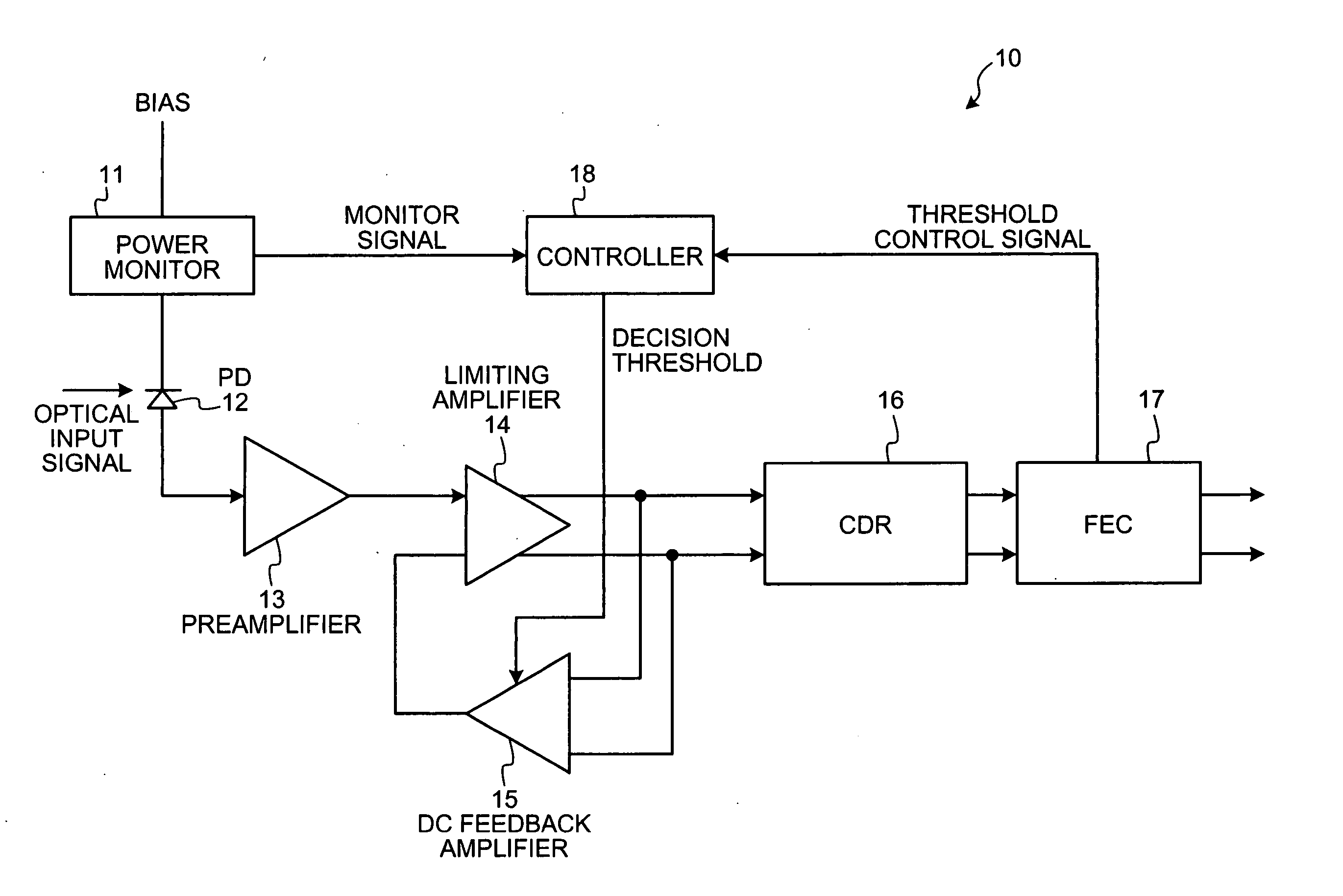
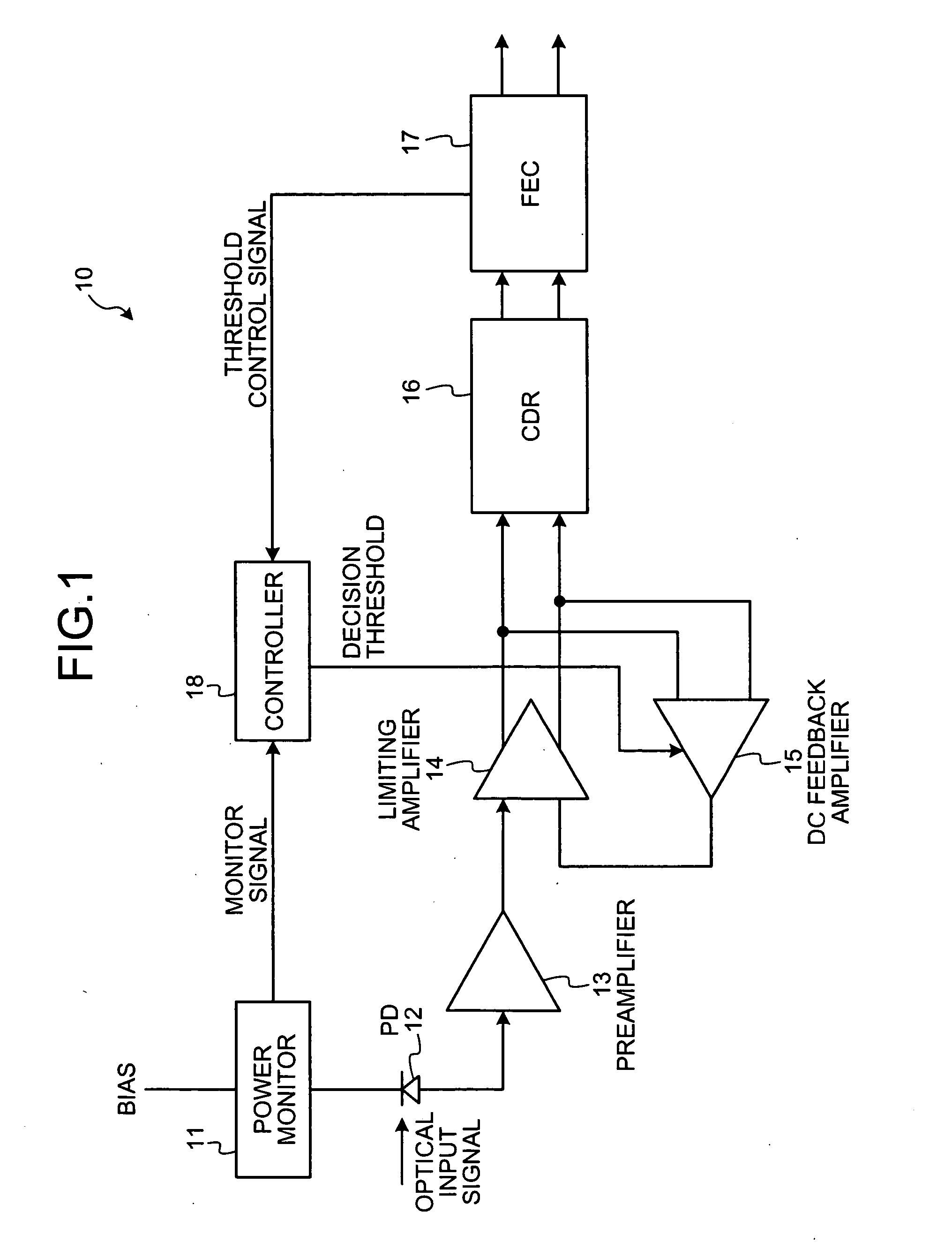
[0031]FIG. 1 is a block diagram of an optical receiver according to the present invention. An optical receiver 10 includes a power monitor 11, a photodiode (PD) 12, a preamplifier 13, a limiting amplifier 14, a direct current (DC) feedback amplifier 15, a clock / data recovery (CDR) 16, a forward error correction (FEC) unit 17, and a controller 18.

[0032] The PD 12 converts an optical input signal into an electrical signal. The preamplifier 13 and the limiting amplifier 14 amplify the electrical signal. An output signal from the preamplifier 13 is input to one of the input terminals of the limiting amplifier 14. The DC feedback amplifier 15 feedbacks an output signal from the limiting amplifier 14 back to the other input terminal of the limiting amplifier 14. Thus, the DC feedback amplifier 15 controls the DC level of the positive signal and the negative signal output from the limiting amplifier 14. The CDR 16 regenerates and retimes the output signal from the limiting amplifier 14.

[0...

fourth embodiment

[0044]FIG. 10 is a block diagram of an optical receiver according to the present invention. An optical receiver 40 shown in FIG. 10 controls, instead of performing the DC feedback control, a DC level of the output signal from the limiting amplifier 14 directly based on the decision threshold calculated the controller 18. The limiting amplifier 14 and the CDR 16 are AC-coupled via capacitors 41 and 42, and the decision threshold calculated by the controller 18 is input to one of the input terminals of the CDR 16 by an adder 43.

[0045]FIG. 11 is a block diagram of an optical receiver according to a fifth embodiment of the present invention. The configuration of an optical receiver 50 shown in FIG. 11 is similar to that of the optical receiver 40 according to the fourth embodiment (see FIG. 10). However, unlike the optical receiver 40, the optical receiver 50 performs the same DC feedback control as that of the first embodiment (see FIG. 1). Specifically, the DC feedback amplifier 15 of...


PUM


Abstract

An optical receiver includes: a converting unit that converts an optical signal into an electrical signal; an amplifying unit that amplifies the electrical signal; a regenerating unit that regenerates the amplified electrical signal; a correcting unit that performs correction of an error included in the regenerated electrical signal; a monitoring unit that performs monitoring of an optical current flowing through the converting unit; and a control unit that calculates a decision threshold based on a result of the correction and a result of the monitoring.

Description

CROSS-REFERENCE TO RELATED APPLICATIONS [0001] This application is based upon and claims the benefit of priority from the prior Japanese Patent Application No. 2005-296535, filed on Oct. 11, 2005, the entire contents of which are incorporated herein by reference. BACKGROUND OF THE INVENTION [0002] 1. Field of the Invention [0003] The present invention relates to an optical receiver that regenerates data from an optical signal based on an optimal decision threshold that is set dynamically according to the receiving power of the optical signal. [0004] 2. Description of the Related Art [0005] With the popularization of the Internet in recent years, data traffic in communication networks has been significantly increasing. To cope with the increase of data traffic, an ultra-broadband photonic network employing a dense wavelength division multiplexing (DWDM) technology has been developed. An ultra-long-haul data communication can be performed with DWDM transmission, which uses an optical ...

Claims


Application Information

Patent Timeline
IPC IPC(8): H04B10/06H04B10/07H03F3/08H04B10/40H04B10/50H04B10/524H04B10/54H04B10/60H04B10/66H04L25/03
CPCH04B10/66
Inventor IDE, SATOSHIYAMABANA, TETSUJI
Owner FUJITSU LTD
Why Eureka
Try Eureka