Chemical protection of metal surface
a metal surface and chemical protection technology, applied in the manufacturing process of electrodes, cell components, cell component details, etc., can solve the problems of battery limitations, drop in charge and discharge capacity, and inability to meet the initial capacity of solid batteries,
- Summary
- Abstract
- Description
- Claims
- Application Information
AI Technical Summary
Benefits of technology
Problems solved by technology
Method used
Image
Examples
example 1
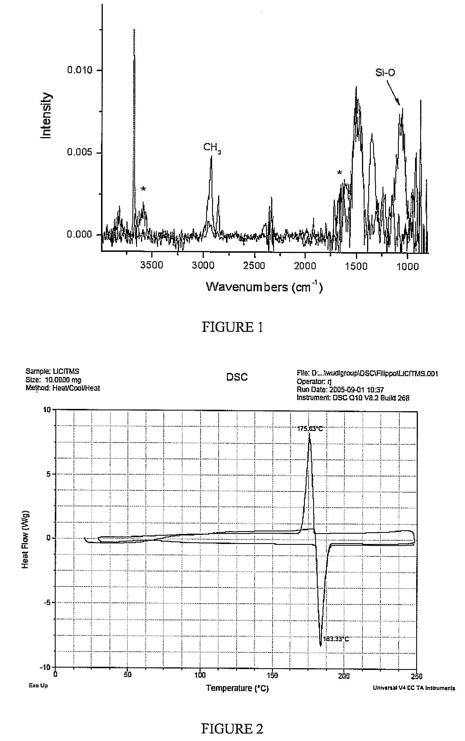
[0028] An untreated sample of the lithium metal and a sample treated with chlorotrimethyl silane for 240 seconds according to the above procedure were analyzed using IR spectroscopy, as shown in FIG. 1. The peak correspond to a lithium hydroxide bond is shown in the 3600 cm−1 range for the untreated sample. This peak is not shown for the treated sample which includes a peak in the 1100 cm−1 range corresponding to a silicon oxygen bond. This relationship indicates the precursor compound has reacted with the metal oxygen containing to form a silicon oxygen bond.
example 2
[0029] An untreated sample of the lithium metal and a sample treated with chlorotrimethyl silane according to the above procedure were analyzed using differential scanning calorimetry, as shown in FIG. 2. The samples were placed in aluminum pans with nitrogen gas flowing around the samples. The samples were heated to above the melting point and cooled below the melting point repetitively to determine whether the lithium was protected from the environment. The untreated lithium sample reacted with the aluminum pan and did not show melting and solidification representative of pure lithium metal. The treated sample, as shown in FIG. 2, exhibits very clear melting and solidification of lithium at or very near the melting point of lithium (the slight amount of superheating or supercooling at the melting point is heating rate dependent). The narrow peaks indicate that the lithium metal is protected and has not reacted with its environment in contrast to the unprotected sample.
example 3
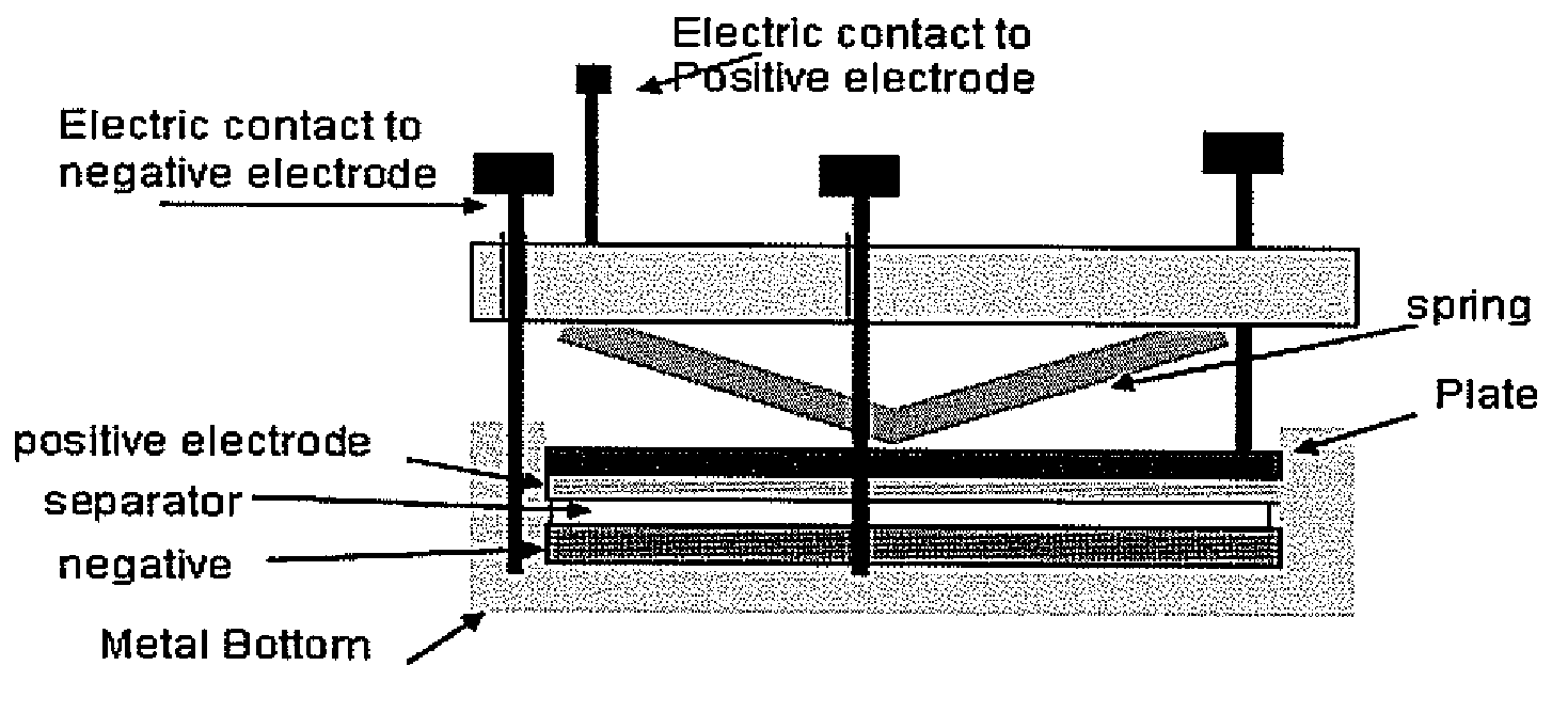
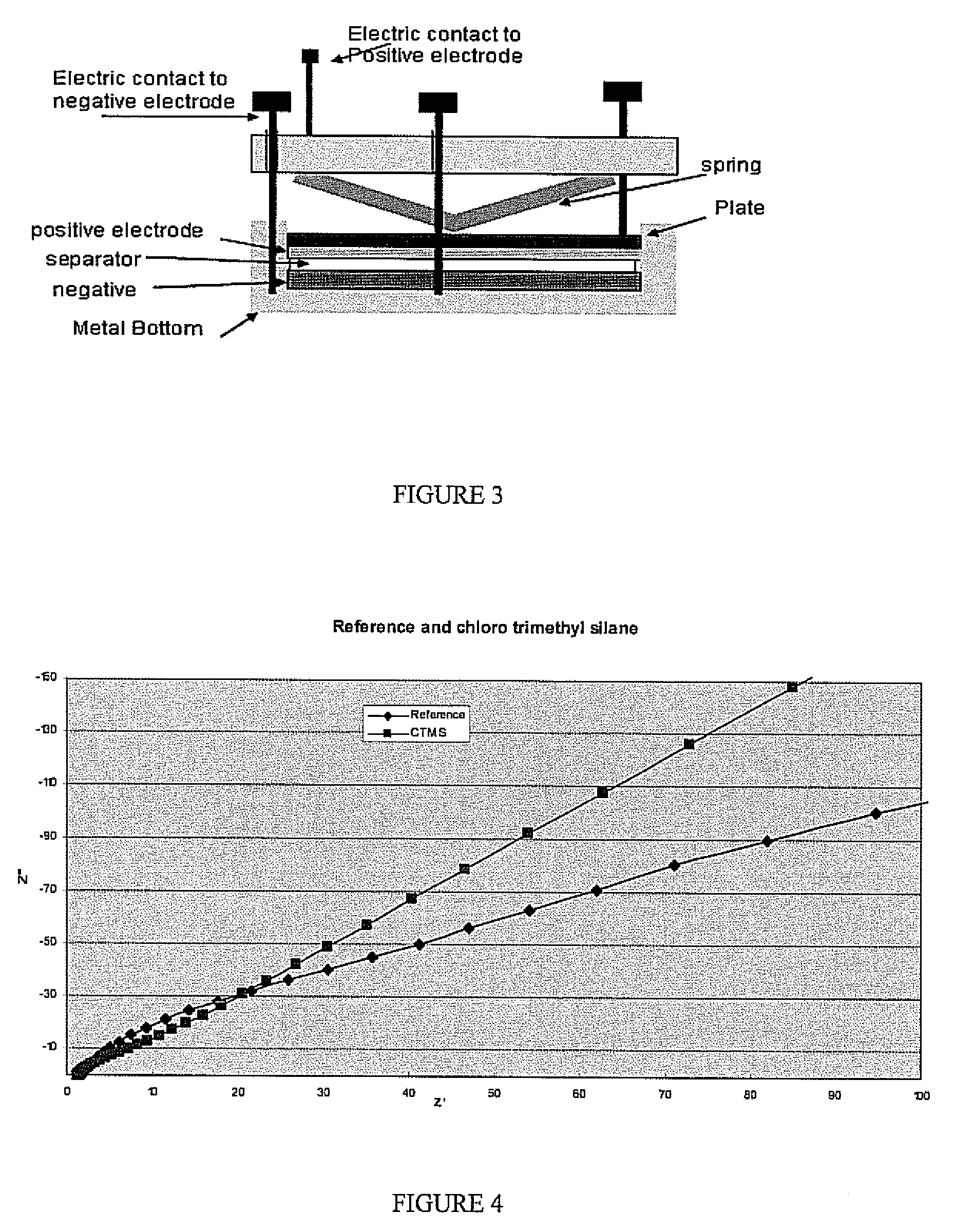
[0030] Impedance tests were performed on various treated samples of lithium and untreated lithium as a reference. The experimental setup used is shown in FIG. 3. The various samples were formed using the procedure described above. The lithium samples were tested in the experimental setup with the sample placed in the positive electrode position. The impedance plots for various samples are shown in FIGS. 4-7. FIG. 4 shows the impedance plot for a sample treated with a chlorotrimethylsilane precursor forming a protective layer. FIG. 5 is a plot of the impedance for a chlorodiisopropylphosphine precursor forming a protective layer. FIG. 6 is a plot of the impedance for a chlorodiethylphosphine precursor forming a protective layer. FIG. 7 is a plot of the impedance for a dibromodimethylborane precursor forming a protective layer. As can be seen in the figures the treated samples all have an impedance curve with a slope less than the reference samples. This behavior indicates an improved...
PUM
| Property | Measurement | Unit |
|---|---|---|
| organo-metallic | aaaaa | aaaaa |
| IR spectroscopy | aaaaa | aaaaa |
| wavelength | aaaaa | aaaaa |
Abstract
Description
Claims
Application Information
 - R&D
- Intellectual Property
- Life Sciences
- Materials
- Tech Scout
- Unparalleled Data Quality
- Higher Quality Content
- 60% Fewer Hallucinations
Browse by: Latest US Patents, China's latest patents, Technical Efficacy Thesaurus, Application Domain, Technology Topic, Popular Technical Reports.
© 2025 PatSnap. All rights reserved.Legal|Privacy policy|Modern Slavery Act Transparency Statement|Sitemap|About US| Contact US: help@patsnap.com


