Method and apparatus for laser welding thermoplastic resin members

a technology of thermoplastic resin and laser welding, which is applied in the direction of chemistry apparatus and processes, lamination ancillary operations, glue vessels, etc., can solve the problems of non-uniform strength in the welded portions of two members, occurrence of burrs, and welded resin burrs on the reduced pressure side of the welded portion, so as to achieve enhanced quality of welded resin members and low facility cost , the effect of high welding strength

Inactive Publication Date: 2007-04-19
TOYOTA JIDOSHA KK +1
View PDF7 Cites 11 Cited by
  • Summary
  • Abstract
  • Description
  • Claims
  • Application Information

AI Technical Summary

Benefits of technology

[0022] With the use of the method and apparatus for laser welding thermoplastic resin members of the present invention, two members formed of thermoplastic resin can uniformly be welded with high welding strength. In addition, since it is possible to prevent burrs from being extruded from th

Problems solved by technology

In the method for laser welding resin components described above, sufficient joining strength can be obtained without using working jigs even in a case where gaps exist between the joining end surfaces; however, nonuniformity in strength might be found in the welded portions of the two members.
In ad

Method used


Image

  • Method and apparatus for laser welding thermoplastic resin members
  • Method and apparatus for laser welding thermoplastic resin members

Examples


Embodiment Construction

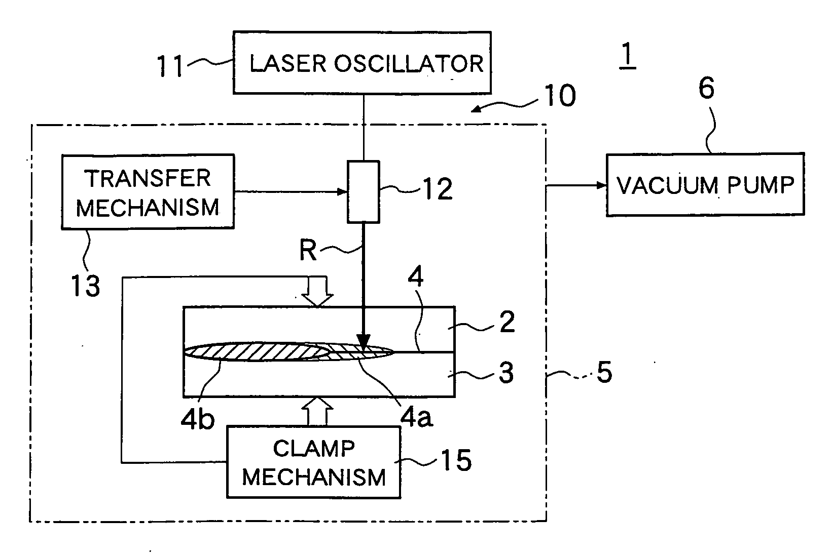
[0025] Hereafter, one embodiment of the apparatus for laser welding thermoplastic resin members according to the present invention will be described in detail based on the drawings. FIG. 1 shows the configuration of the main part of the apparatus for laser welding thermoplastic resin members according to the present embodiment.

[0026] In FIG. 1, with a laser welding apparatus 1 for thermoplastic members of the present embodiment, a first member 2 formed of transmissive thermoplastic resin that transmits a laser beam and a second member 3 formed of absorptive thermoplastic resin that absorbs a laser beam are made to come into contact with each other, and contact surfaces 4 are joined by melting using a laser beam. Further, the laser welding apparatus 1 is a welding apparatus wherein the first member and the second member are made to come into contact with each other under a reduced pressure atmosphere, and contact surfaces 4 of the two members are irradiated with a laser beam generat...


PUM

PropertyMeasurementUnit
Pressureaaaaaaaaaa
Electrical conductivityaaaaaaaaaa
Strengthaaaaaaaaaa

Abstract

A method and apparatus for laser welding, whereby high welding strength, a low degree of variation in strength, and lack of occurrence of burrs can be achieved when two members formed of thermoplastic resin material are welded, are provided. In a laser welding apparatus 1, contact surfaces 4 of a first member 2 formed of transmissive thermoplastic resin that transmits a laser beam and a second member 3 formed of absorptive thermoplastic resin that absorbs a laser beam are joined by melting via laser beam R. The apparatus is equipped with a casing 5 that accommodates the first member and the second member, a vacuum pump 6 that reduces the pressure inside the casing, and a laser beam generator 10, whereby at least one of the contact surfaces of the first member and the second member becomes melted. In the apparatus, the first member and the second member are made to come into contact with each other under a reduced pressure atmosphere, and contact surfaces of the two members are irradiated with laser beam R from the side of the first member that transmits laser beam.

Description

BACKGROUND OF THE INVENTION [0001] 1. Field of the Invention [0002] The invention relates to a method and apparatus for laser welding thermoplastic resin members. In particular, the invention relates to a method and apparatus for joining a member formed of a transmissive thermoplastic resin that transmits a laser beam with a member formed of an absorptive thermoplastic resin that absorbs a laser beam by melting them. [0003] 2. Background Art [0004] In response to the demand in recent years for reducing the weight and cost of components in various fields, such as automobile components, such components are often made of resin materials and formed as resin molded items. When a resin molded item having a complex shape is to be formed, a plurality of component parts of the resin molded item are molded in advance and then jointed together by welding for productivity enhancing purposes. [0005] As an example of a conventional method for welding such resin molded items, the method for laser ...

Claims


Application Information

Patent Timeline
IPC IPC(8): B32B37/00B29C65/16
CPCB29C65/1606B29C66/934B29C65/1635B29C66/001B29C66/00141B29C66/341B29C66/8242B29C66/8266B29C66/82661B29C66/929B29C66/939B29C66/00145B29C65/1654B29C65/1677B29C65/1687B29C66/9161B29C66/919B29C65/1616B29C66/73921B29C66/73774B29C66/863B29C66/83221B29C66/71B29C65/16B29C65/14
Inventor NAKAJIMA, KATSUHIKOWATANABE, TOSHIONAKAMURA, HIDEOMORI, HIROSHIFUJITA, SUSUMUNAKATANI, MITSUNOBU
Owner TOYOTA JIDOSHA KK
Why Eureka
Try Eureka