
Compact single mandrel creel for over end take-off thread delivery

a single mandrel, thread technology, applied in the direction of looms, thin material processing, textiles and papermaking, etc., can solve the problems of unproductive downtime, insufficient configuration of two yarn packages tied together, and the shutdown of the manufacturing process, so as to improve the number of packages, improve the quality of the finished product, and improve the effect of quality

Inactive Publication Date: 2007-04-19
INVISTA NORTH AMERICA R L
View PDF9 Cites 30 Cited by
  • Summary
  • Abstract
  • Description
  • Claims
  • Application Information

AI Technical Summary

Benefits of technology

[0015] The present invention compact creel using the OETO method that accommodates an increased number of packages in a relatively small footprint while providing a straight in-line delivery path in which fiber bends and changes in direction are minimized. In addition, the present invention is a system, apparatus and method for tension control in a fiber feeding system that provides a fast and reliable method for feeding high tack elastomeric thread or fiber from a package to a manufacturing process. Furthermore, the present invention provides a method and apparatus for changing packages on a creel without interrupting the manufacturing process. In particular, the compact creel of the present invention provides for continuous operation of unwinding and fiber delivery by allowing a standby package to be loaded on the same mandrel as an active package that is presently being unwound.

Problems solved by technology

This shut down of the manufacturing process in the problem of unproductive downtime on a manufacturing line using the RTO method.
However, with the advent of higher speed manufacturing processes, a configuration of two yarn packages tied together has become increasingly insufficient to supply the associated machinery, and creels with arrangements of four yarn packages tied together have been provided.
However, a problem with carousel and other creels that handle a large number of packages is that the fibers must undergo several changes in direction as it is fed from the packages to other associated machinery.
Each time the fiber changes direction, particularly sharply, the chances of a fiber break are greatly increased because of the increased tension resulting from the changes in direction.
Fiber breaks with such creels also cause interruptions in the manufacturing process and lead to the problem of unproductive downtime discussed above.
An additional problem with creels using multiple packages is related to the size of the yarn packages which can be provided and supported on a creel.
That is, the amount of yarn is limited due to practicalities such as weight and space occupied by the package.
However, a large number of packages of this size package can take up a lot of valuable manufacturing floor space when used with creel configurations of the background art.
However, as noted above, a problem with OETO creels with this type of configuration is the valuable floor space they take up in the manufacturing environment.
In addition, unacceptable variations in threadline tension are common with these background art creels when using the OETO method.
However, the '574 patent does not disclose the concept of utilizing a variable speed electrical motor for a driven roll, where the speed of the motor is determined based on a range of desired thread tensions and could improve the performance of the manufacturing process.
The aforementioned problems make the continuous processing of high tack, elastomeric fibers particularly problematic.
However, both approaches add additional expense to the manufacturing process.

Method used


Image

  • Compact single mandrel creel for over end take-off thread delivery
  • Compact single mandrel creel for over end take-off thread delivery
  • Compact single mandrel creel for over end take-off thread delivery

Examples


first embodiment

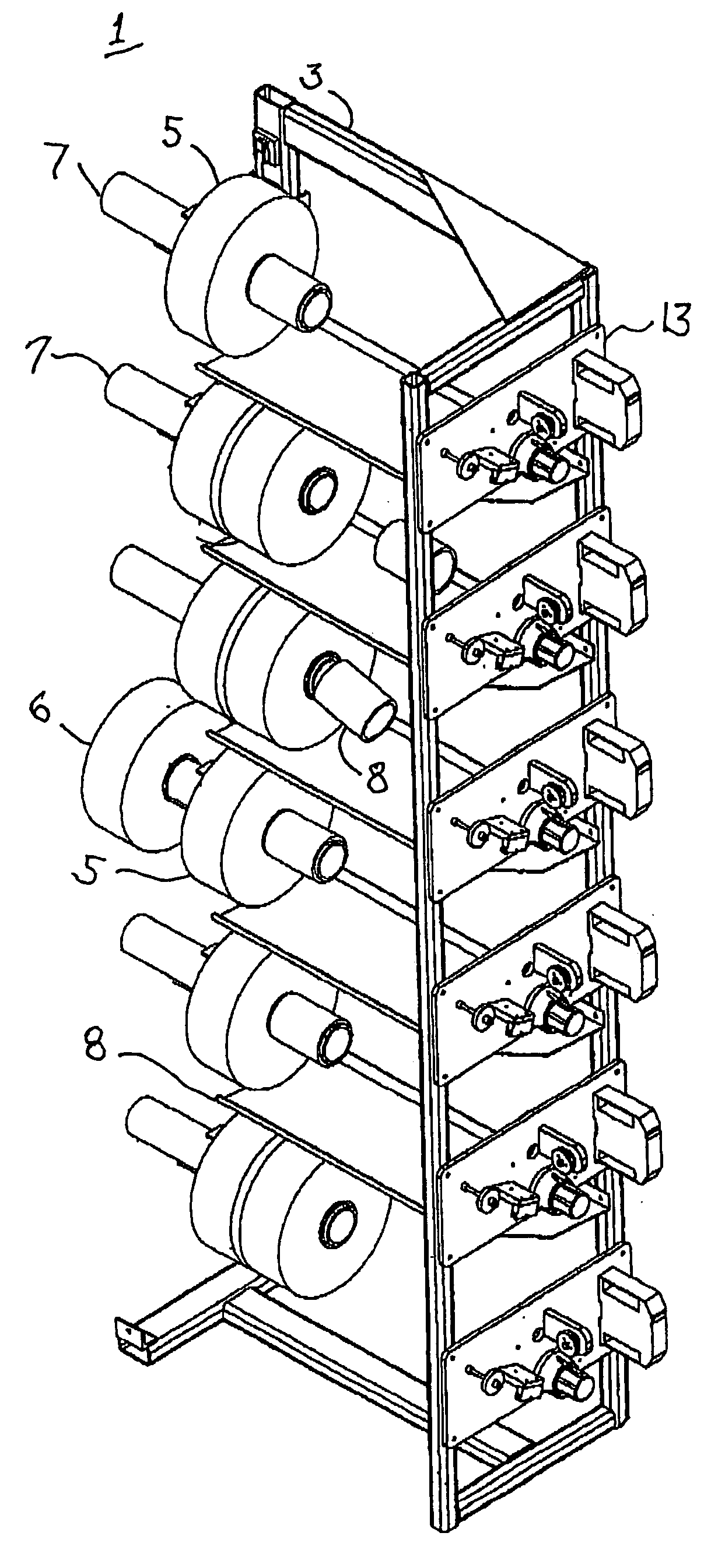
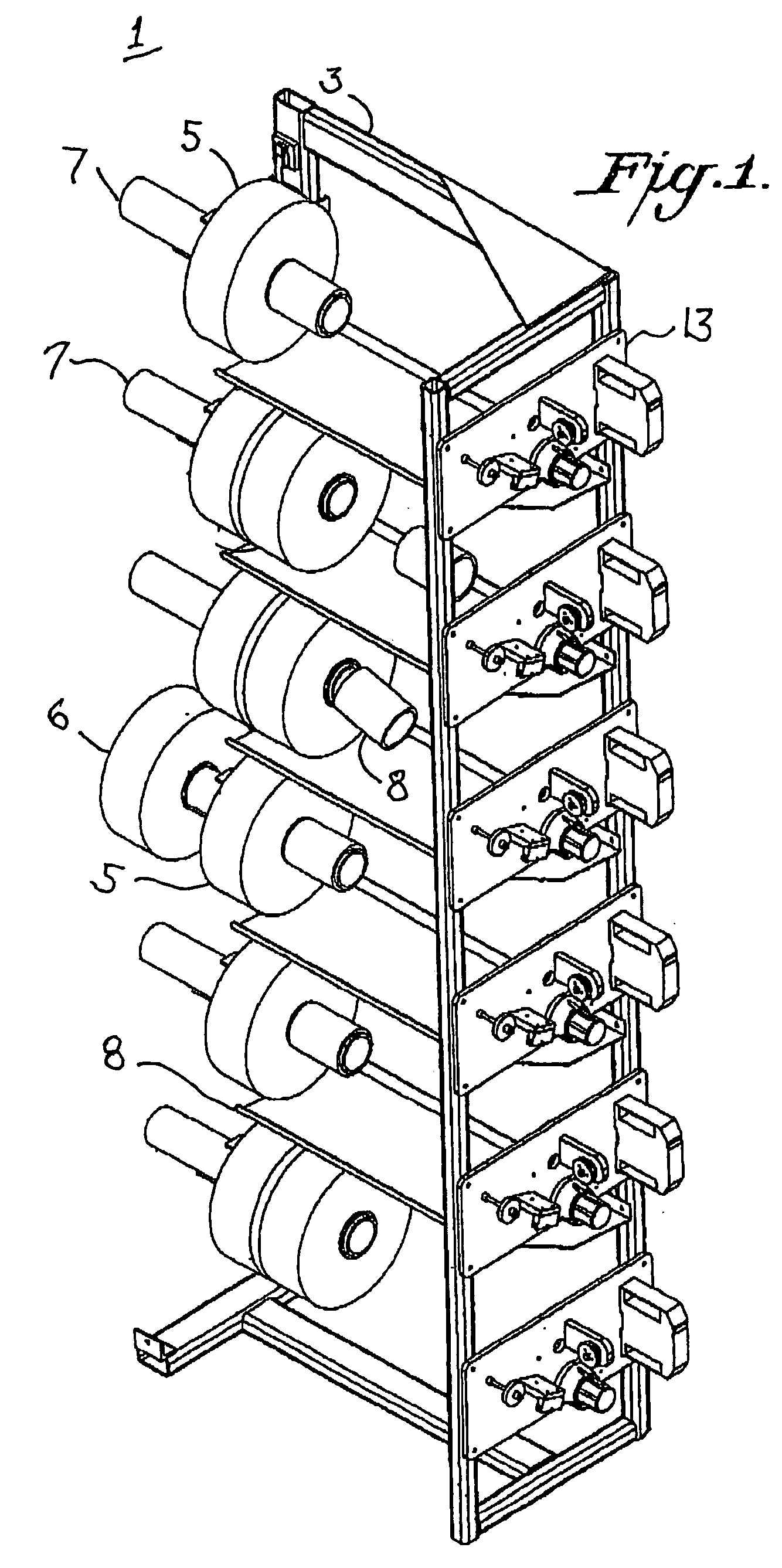
[0052] With reference to FIG. 1, a compact creel system 1 of the present invention is shown from a front perspective view. As shown in FIG. 1, a frame 3 of the creel system 1 supports each package 5, 6 with a single mandrel 7 or cylindrical rod in a preferably in-line orientation. The diameter of the mandrel 7 is smaller than the diameter of the open core 8 of the packages 5, 6 such that the packages 5, 6 can slide over the mandrel 7 and such that the thread or fiber can be unwound from the active package 5 by the OETO method.

[0053] In addition, the interior of the mandrel 7 is configured to accommodate the insertion of a package change fixture 21 that allows positioning and loading of at least one standby package 6 on each mandrel 7 of the creel while fiber is being unwound from an active package 5. For example, by making the mandrel 7 hollow, the mandrel can accommodate the insertion of a package change fixture. Further the compact creel system 1 includes a tray 9 that can catch t...

second embodiment

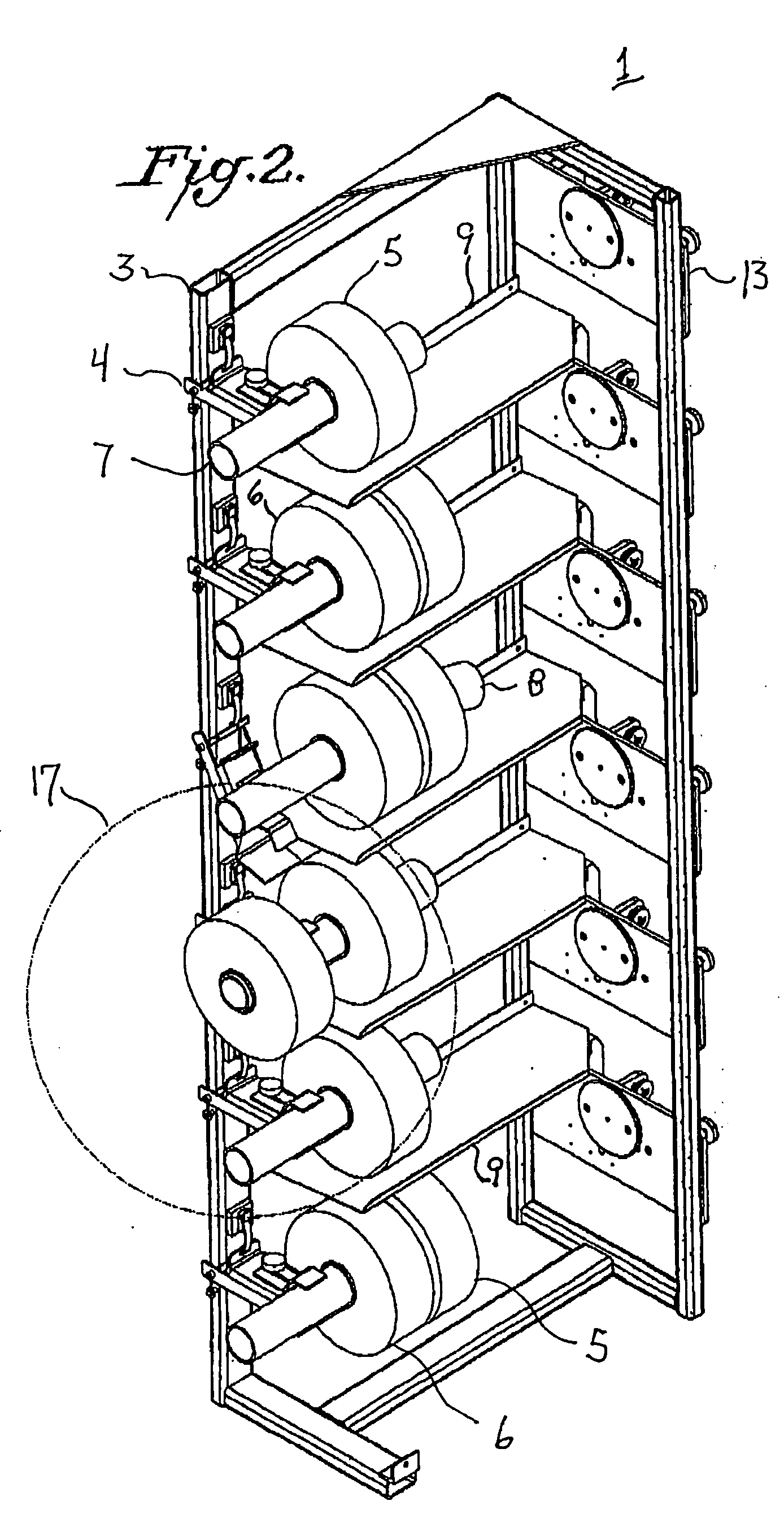
[0061]FIG. 7 is a front perspective view of the present invention. As shown in FIG. 7, a frame 3 of the creel system 1 supports each package 5, 6 with a single mandrel 7 or cylindrical rod in a preferably in-line orientation. The diameter of the mandrel 7 is smaller than the diameter of the open core 8 of the package 5 such that the package 5, 6 can slide over the mandrel 7 and such that the thread or fiber can be unwound from the active package 5 by the OETO method.

[0062] In addition, the interior of the mandrel 7 is configured to accommodate the insertion of a package change fixture 21 that allows positioning and loading at least one standby package 6 on each mandrel 7 of the compact creel while fiber is being unwound from an active package 5. For example, this may be accomplished by making the mandrel 7 hollow. Further, the compact creel system 1 may include trays 9 (not shown) that can catch an exhausted core 8 of a previously active package 5 for later disposal.

[0063] Further,...


PUM


Abstract

The present invention compact creel using the OETO method that accommodates an increased number of packages in a relatively small footprint while providing a straight in-line delivery path in which fiber bends and changes in direction are minimized. In addition, the present invention is a system, apparatus and method for tension control in a fiber feeding system that provides a fast and reliable method for feeding high tack elastomeric thread or fiber from a package to a manufacturing process. Furthermore, the present invention provides a method and apparatus for changing packages on a creel without interrupting the manufacturing process. In particular, the compact creel of the present invention provides for continuous operation of unwinding and fiber delivery by allowing a standby package to be loaded on the same mandrel as an active package that is presently being unwound.

Description

CROSS-REFERENCE TO RELATED APPLICATION [0001] This application claims benefit of priority from Provisional Application No. 60 / 724,796 filed Oct. 11, 2005.BACKGROUND OF THE INVENTION [0002] 1. Field of the Invention [0003] The present invention relates to a thread delivery system or fiber unwinding device, and more specifically to a compact creel system or device for continuous delivery of threads or fibers to a downstream fiber manufacturing process or device. [0004] 2. Description of Background Art [0005] Creels are well known in the background art and support packages upon which thread, fiber or yarn is wound for delivery to an associated manufacturing device such as a loom or a diaper machine (note: the terms “thread,”“fiber” and “yarn” are used interchangeably throughout this document). The most common method of unwinding yarn from a cylindrical mandrel (i.e., a “package”) on a creel in manufacturing processes is referred to as “rolling take-off” (RTO) method. In the RTO method,...

Claims


Application Information

Patent Timeline
IPC IPC(8): B65H67/02
CPCB65H49/12B65H49/16B65H2701/31D02H1/00D03D47/34
Inventor HEANEY, DANIEL J.HICKS, DENNISGRAVERSON, JON P.SHACKLETON, JEFFDE MOEL, PAUL
Owner INVISTA NORTH AMERICA R L
Learn More