Tilted combiners/decombiners and photonic integrated circuit (PIC) employing the same
What is Al technical title?
Al technical title is built by PatSnap Al team. It summarizes the technical point description of the patent document.
a technology of combiners/decombiners and integrated circuits, applied in the field of combiners/decombiners, can solve the problem that no longer can be deployed as optical inputs to combiners, and achieve the effect of enhancing power uniformity
Inactive Publication Date: 2007-04-19
INFINERA CORP
View PDF14 Cites 11 Cited by
Summary
Abstract
Description
Claims
Application Information
AI Technical Summary
This helps you quickly interpret patents by identifying the three key elements:
Problems solved by technology
Method used
Benefits of technology
[0023] According to this invention, a monolithic optical transmitter photonic integrated circuit (TXPIC) comprises a plurality of integrated modulated sources having an array of laser sources with power outputs, at constant current, varying across the array similar to a quadratic-shaped curve and, further, forming an array of signal channels each having a different wavelength output which are a series of regularly spaced wavelengths. An optical combiner/decombiner is integrated in the circuit and has at least one free space region to receive a plurality of waveguides each respectively carrying a signal wavelength output from a modulated source. The optical combiner/decombiner may be of the non-reflective or transmissive type or of the reflective type. The free space region has a plurality of ordered bands along its edge where the zero order band is substantially at a longitudinal centerline of the free space region where, on either side of this ban
Problems solved by technology
In other words, if one of the inputs to a conventional reflective-type selective wavelength comb
Method used
Image
Click on the blue label to locate the original text in one second.
Reading with bidirectional positioning of images and text.
Examples
second embodiment
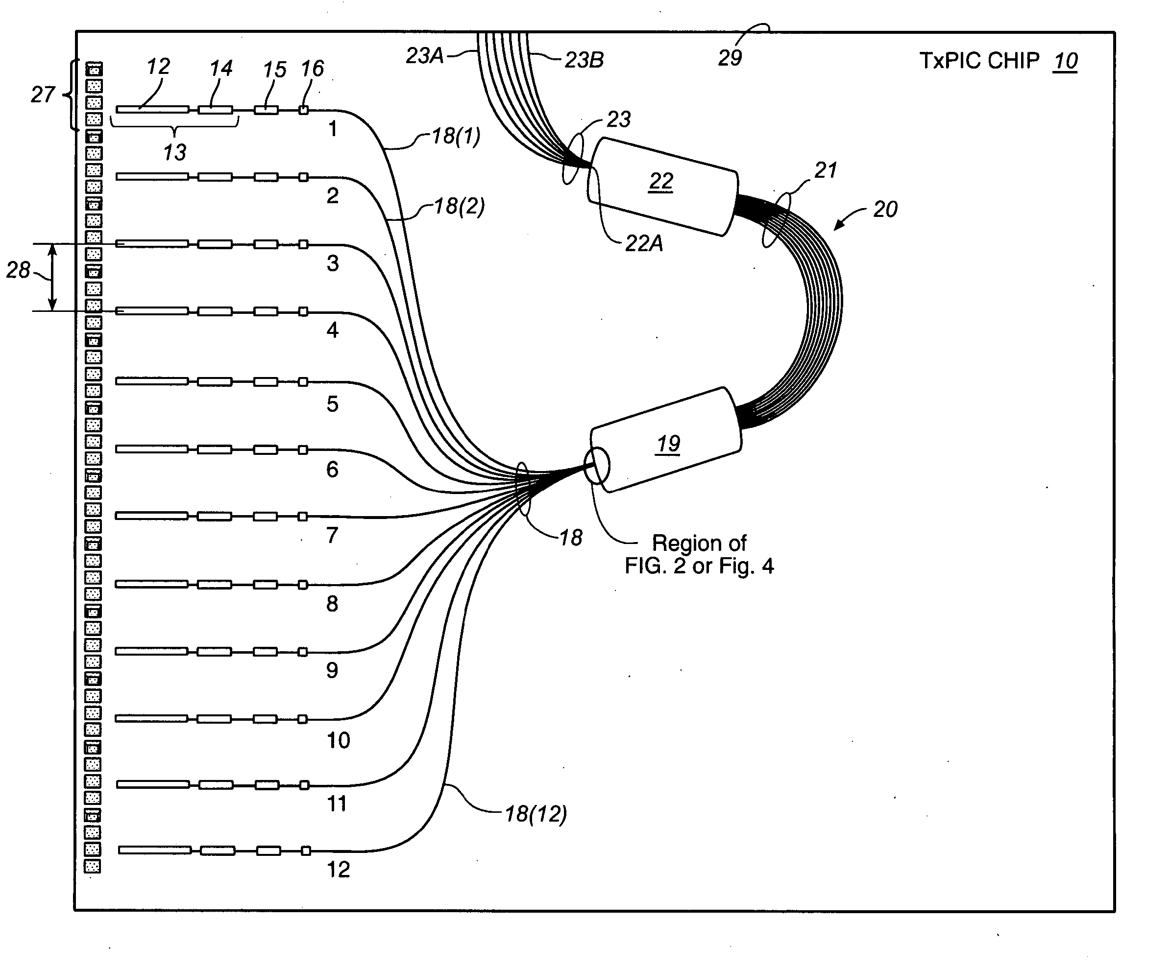
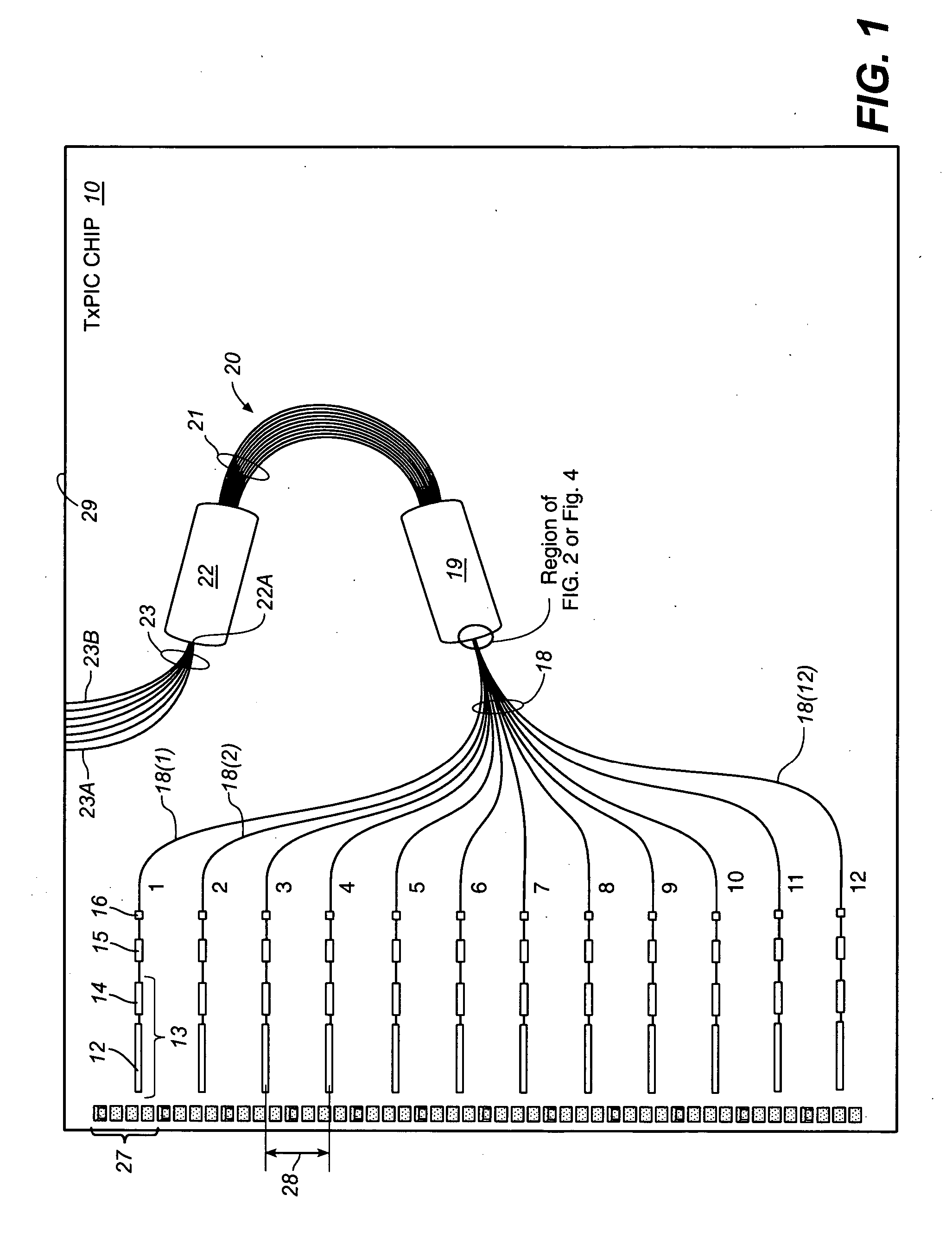
[0044] Reference is now made to this invention shown in FIGS. 6 and 7. TxPIC 60 in FIG. 6 comprises a plurality of integrated modulated sources 13 for providing channel signals on output waveguides 18 comprising channels Nos. 1-12. Each channel waveguide 18(1) . . . 18(12) is provided to an input / output free space region 64 of a reflective combiner 62 comprising, here, a reflective-type AWG. A reflective-type AWG is illustrated in the art as seen in U.S. Pat. No. 5,396,507 at device 7, which patent is incorporated herein by its reference. Reflective AWG 62 is optically the same as AWG 20 in FIG. 1 but physically different in construction in that the arrayed waveguide grating arms 63 approximate one-half the grating arms 21 of AWG 20 so that a single free space region 64 functions both as the input free space region 19 as well as output free space region 22 of AWG 20 of FIG. 1. A unique feature of reflective AWG 62 is that a portion 65 of grating arms 63 are substantially straight in...
PUM
Abstract
A monolithic optical transmitter photonic integrated circuit (TXPIC) comprises a plurality of integrated modulated sources which, when all operated at constant current, display a power output that varies as a function of array position similar to a quadratic-shaped curve and, further, forming an array of signal channels each having a different wavelength output. An optical combiner/decombiner is integrated in the circuit and has at least one free space region with a plurality of ordered bands along its edge where the zero order band is substantially at a longitudinal centerline of the free space region and where, on either side of this band, is a first order band followed by additional higher order bands. The ends of the output waveguides from the modulated sources are coupled approximate to the free space region edge along a region of the zero order band between one of the adjacent first order bands and a longitudinal centerline of the zero order band so that the inputs of the signal channels to the combiner of are titled or offset with respect to the longitudinal centerline of the combiner free space region so the combined outputs from the optical combiner will be aligned along the slope of the quadric-shaped curve of the combiner output passband envelope. The tilted combiner/decombiner may also be deployed in a receiver photonic integrated circuit (RxPIC) or other circuit employing such a device.
Description
CROSS REFERENCE TO RELATED APPLICATIONS [0001] This application claims priority of provisional application, Ser. No. 60 / 663,279, filed Mar. 18, 2005 and, further, is a continuation-in-part of patent application, Ser. No. 10 / 846,336, filed May 13, 2004 and entitled, TRANSMITTER AND RECEIVER PHOTONIC INTEGRATED CIRCUIT (TXPIC AND RXPIC) CHIPS UTILIZING COMPACT WAVELENGTH SELECTIVE COMBINERS / DECOMBINERS and published on Oct. 28, 2004 as Publication No. US 2004 / 0213582 A1, which claims priority to provisional application, Ser. No. 60 / 470,570, filed Apr. 14, 2003, which application is also incorporated herein by its reference, and is also a continuation-in-part of patent applications, Ser. No. 10 / 267,331, filed Oct. 8, 2002, also published on May 22, 2003 as Publication Ser. No. US 2003 / 0095737 A1, and entitled, TRANSMITTER PHOTONIC INTEGRATED CIRCUITS (TXPIC) AND OPTICAL TRANSPORT NETWORKS EMPLOYING TxPICs; Ser. No. 10 / 267,304, filed Oct. 8, 2002, also published on Feb. 19, 2004 as Publ...
Claims
Application Information
Patent Timeline
Application Date:The date an application was filed.
Publication Date:The date a patent or application was officially published.
First Publication Date:The earliest publication date of a patent with the same application number.
Issue Date:Publication date of the patent grant document.
PCT Entry Date:The Entry date of PCT National Phase.
Estimated Expiry Date:The statutory expiry date of a patent right according to the Patent Law, and it is the longest term of protection that the patent right can achieve without the termination of the patent right due to other reasons(Term extension factor has been taken into account ).
Invalid Date:Actual expiry date is based on effective date or publication date of legal transaction data of invalid patent.