Active clearance control system for gas turbine engines

a technology of active clearance control and gas turbine engine, which is applied in the direction of machines/engines, liquid fuel engines, lighting and heating apparatus, etc., can solve the problems of adding weight to the engine structure and introducing additional parts, and achieve the effect of increasing the clearance distan

Active Publication Date: 2007-04-19
RTX CORP
View PDF6 Cites 26 Cited by
  • Summary
  • Abstract
  • Description
  • Claims
  • Application Information

AI Technical Summary

Benefits of technology

[0008] In accordance with the present invention, a method for actively controlling clearances within a gas turbine engine broadly comprises the steps of introducing a quantity of working fluid into an integrated manifold mounted to a turbine of a gas turbine engine; circulating the working fluid throughout the integrated manifold and into the turbine; and increasing a clearance distance between two components of the turbine.

Problems solved by technology

These multiple parts not only add weight to the engine structure but also introduce additional parts that may expand and contract under the extreme operating environment.

Method used


Image

  • Active clearance control system for gas turbine engines
  • Active clearance control system for gas turbine engines
  • Active clearance control system for gas turbine engines

Examples


Embodiment Construction

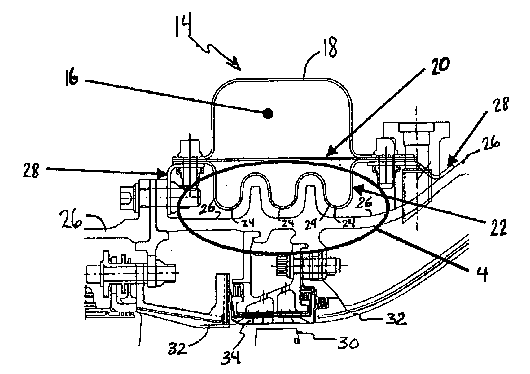
[0015] The active clearance control system described herein employs a single structure capable of being integrated into a gas turbine engine to supply, distribute and deliver working fluid while minimizing both weight and costs. The single structure also shields the engine components from harsh external environment of uneven temperatures and pressures. In addition, the single structure is spatially economical and can accommodate extra insulation and / or shielding if required. For purposes of explanation of the present invention, by “working fluid” means fluid supplied from the atmosphere and / or through one or more components of the gas turbine engine that enters the active clearance control system and possesses a temperature below the engine operating conditions or a temperature above the engine operating conditions.

[0016] The active clearance control system described herein generally comprises an integrated manifold having a plenum defined by a manifold disposed opposite a shieldin...


PUM


Abstract

A gas turbine engine generally includes a compressor, a combustor, and a turbine. The turbine can include an integrated manifold comprising a plenum defined by a manifold disposed in connection with a divider plate and opposite a shielding plate comprising a plurality of apertures. The integrated manifold also includes a means for integrally mounting the manifold to the turbine. During operation of the gas turbine engine, a quantity of working fluid enters the integrated manifold and circulates throughout the plenum and shielding plate, and enters the turbine through the apertures to actively control clearances between turbine engine components.

Description

FIELD OF USE [0001] This disclosure relates to gas turbine engines and, more particularly, relates to active clearance control systems for gas turbine engines. BACKGROUND OF THE INVENTION [0002] The control of the radial clearance between the tips of rotating blades and the surrounding annular shroud in axial flow gas turbine engines is one known technique for proving engine efficiency. By reducing the blade tip to shroud clearance, designers can reduce the quantity of turbine working fluid which bypasses the blades, thereby increasing engine power output for a given fuel or other engine input. [0003]“Active clearance control” refers to those clearance control arrangements wherein a quantity of working fluid is employed by the clearance control system to regulate the temperature of certain engine structures and thereby control the blade tip to shroud clearance as a result of the thermal expansion or contraction of the cooled structure. It is a feature of such active clearance contro...

Claims


Application Information

Patent Timeline
Patent Type & Authority Applications(United States)
IPC IPC(8): F01D11/08
CPCF01D11/24F05D2250/61F05D2250/611Y02T50/60
Inventor PEZZETTI, MICHAEL C. JR.KANE, DANIEL E.PEASE, CRAIG B.REINARD, JOHN T. JR.
Owner RTX CORP
Why Eureka
Try Eureka