Method for controlling a fuel mixture, exhaust gas system having a mobile internal combustion engine and vehicle having an exhaust gas system

a technology of exhaust gas and fuel mixture, which is applied in the direction of electric control, machines/engines, instruments, etc., can solve the problems of some sluggish thermal behavior and achieve the effect of simple structure and cost-effectiveness

Inactive Publication Date: 2007-04-26
EMITEC GESELLSCHAFT FUR EMISSIONSTECHNOLOGIE MBH
View PDF22 Cites 11 Cited by
  • Summary
  • Abstract
  • Description
  • Claims
  • Application Information

AI Technical Summary

Benefits of technology

[0012] It is accordingly an object of the invention to provide a simplified method for controlling a fuel mixture with a control probe in an exhaust gas system of a mobile internal combustion engine, an exhaust gas system having a mobile internal combustion engine, being cost-effective and having a simple structure, and a vehicle having an exhaust gas system, which at least partially alleviate the hereinafore-mentioned disadvantages of the heretofore-known methods and devices of this general type.
[0018] When the internal combustion engine is (re)started, the exhaust gas flowing through the catalytic converter then gradually heats the carrier body of the catalytic converter and the coating. In the process, a temperature profile forms in the direction of flow of the exhaust gas in the catalytic converter so that at first the highest temperatures are present at the exhaust gas inlet side and those temperatures then decrease in the direction of flow. In this case, it is then proposed in particular that the control probe already have a temperature of at least 70° C., in particular of at least 90° C. [degrees Celsius], before the catalytic converter or the carrier body of the catalytic converter in a plane parallel to the gas inlet side at a distance of 10 mm, has reached a temperature of 95° C. The accumulated water increasingly vaporizes in a range above an average of 95° C. and propagates in the direction of flow of the catalytic converter, and it condenses again if it arrives at colder regions. In this way, a type of “water vapor front” is generated through the catalytic converter. By ensuring a certain temperature of the control probe, it is made certain that the control probe does not constitute such a heat sink when in contact with the water vapor front that water condenses. This ensures the functionality of the individual control probe.
[0020] In accordance with an added mode of the invention, the control probe is a lambda probe being simultaneously used to check the conversion capability of the at least one catalytic converter. In particular, this is what is referred to as a broadband lambda probe (lambda probe) which outputs a continuous, for example linear, output signal as a function of the oxygen content in the exhaust gas in the range around lambda=1 (for example with a tolerance of ±0.005). This signal is used to control the mixture in accordance with the predefined setpoint or desired values. With the embodiment of the control probe proposed in this case, it is possible to locate the probe relatively far down in the catalytic converter, in particular at a distance of 25 mm to 60 mm. In this region, the lambda oscillations are frequently already reduced or smoothed by more than 50%, in some cases even by more than 90%. The use of such a broadband lambda probe also to the same extent permits a high degree of measuring accuracy, and an extremely low tendency to poisoning occurs by virtue of its position in the catalytic converter, so that a mean value for lambda can also be found to occur precisely and over a relatively long time period. The oxygen content determined with the lambda probe can additionally also be used as a measure of the conversion capability of the catalytic converter. Reference is made to the explanations given at the beginning with respect to this process. It is possible to easily carry out onboard diagnostics with such a lambda probe. As a result, a method is specified which has a particularly simple structure and at the same time permits lambda control of the internal combustion engine and onboard diagnostics.
[0024] The measurement results of the control probe are evaluated through the use of the control unit and primarily the composition of the fuel mixture or else also the ignition time, the injection pressures, etc. are varied in accordance with predefined setpoint values stored there. As a result, the system of a control probe disposed upstream and a trimming probe disposed downstream is dispensed with and replaced by a system including an individual control probe which projects into internal regions of the at least one catalytic converter. This significantly reduces the susceptibility to faults, the technical complexity and the costs.
[0041] As a further measure it is also possible for the catalytic converter to be constructed with a metallic catalyst carrier body. In this case, metallic channel walls with a thickness in the range of from 40 μm to 110 μm (micrometers) are preferred. These in turn make available the favorable, high thermal capacity which prevents rapid vaporization of adsorbed or absorbed water.
[0047] The water impacts can advantageously be prevented if the protective cap heats up more quickly than the honeycomb structure or the honeycomb body into which the measuring sensor is inserted. The protective cap preferably reaches, as quickly as possible, a temperature at which condensing out of water vapor on the surface of the measuring sensor is reliably avoided. This is achieved, for example, by virtue of the fact that the protective cap is formed from a material which has a significantly lower thermal capacity, in particular specific thermal capacity, than the material from which the honeycomb body is formed. A material is preferably selected which has a specific thermal capacity such that in the normal operating state it is ensured that if the honeycomb body is at a temperature above the boiling point of water in the direction of flow upstream of the measuring sensor, the protective cap is also at a temperature above the boiling point of water, specifically even if the honeycomb body is still at a temperature below the boiling point of water directly adjacent the measuring sensor downstream of the honeycomb body in the direction of flow. To the same extent, it is advantageous that if the honeycomb body is at a temperature above the boiling point of water upstream of the measuring sensor in the direction of flow, the thermal capacity, in particular specific thermal capacity of the protective cap, is selected such that it is at such a temperature that under specific operating conditions the dew point of water on the measuring sensor or the protective cap is reliably avoided, thus effectively avoiding the condensing out of water on the measuring sensor or the protective cap.

Problems solved by technology

In particular, it is a thermal mass so that in this case a somewhat sluggish thermal behavior occurs.

Method used


Image

  • Method for controlling a fuel mixture, exhaust gas system having a mobile internal combustion engine and vehicle having an exhaust gas system
  • Method for controlling a fuel mixture, exhaust gas system having a mobile internal combustion engine and vehicle having an exhaust gas system
  • Method for controlling a fuel mixture, exhaust gas system having a mobile internal combustion engine and vehicle having an exhaust gas system

Examples


Embodiment Construction

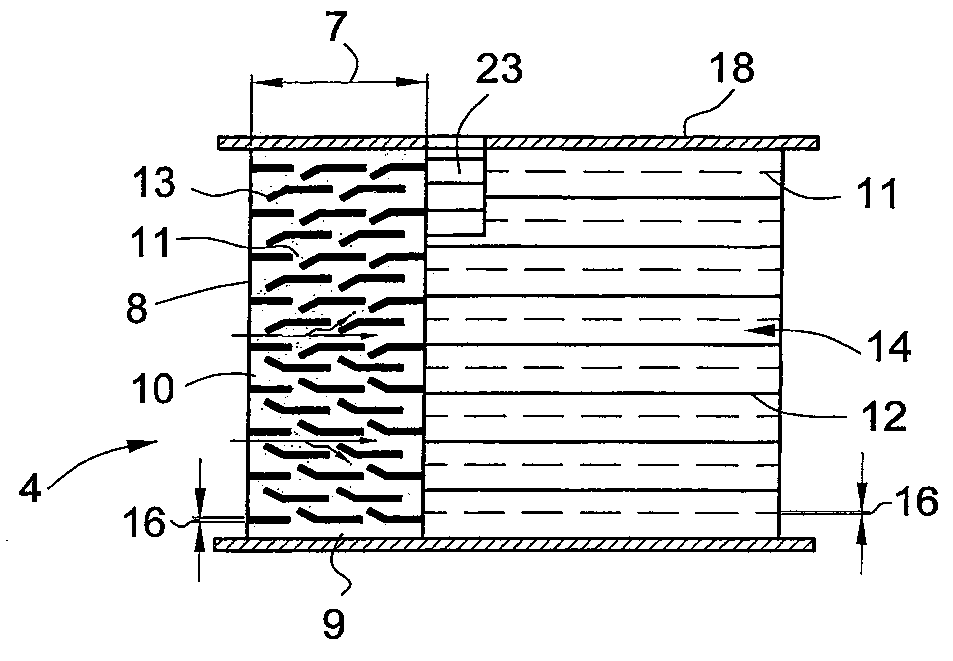
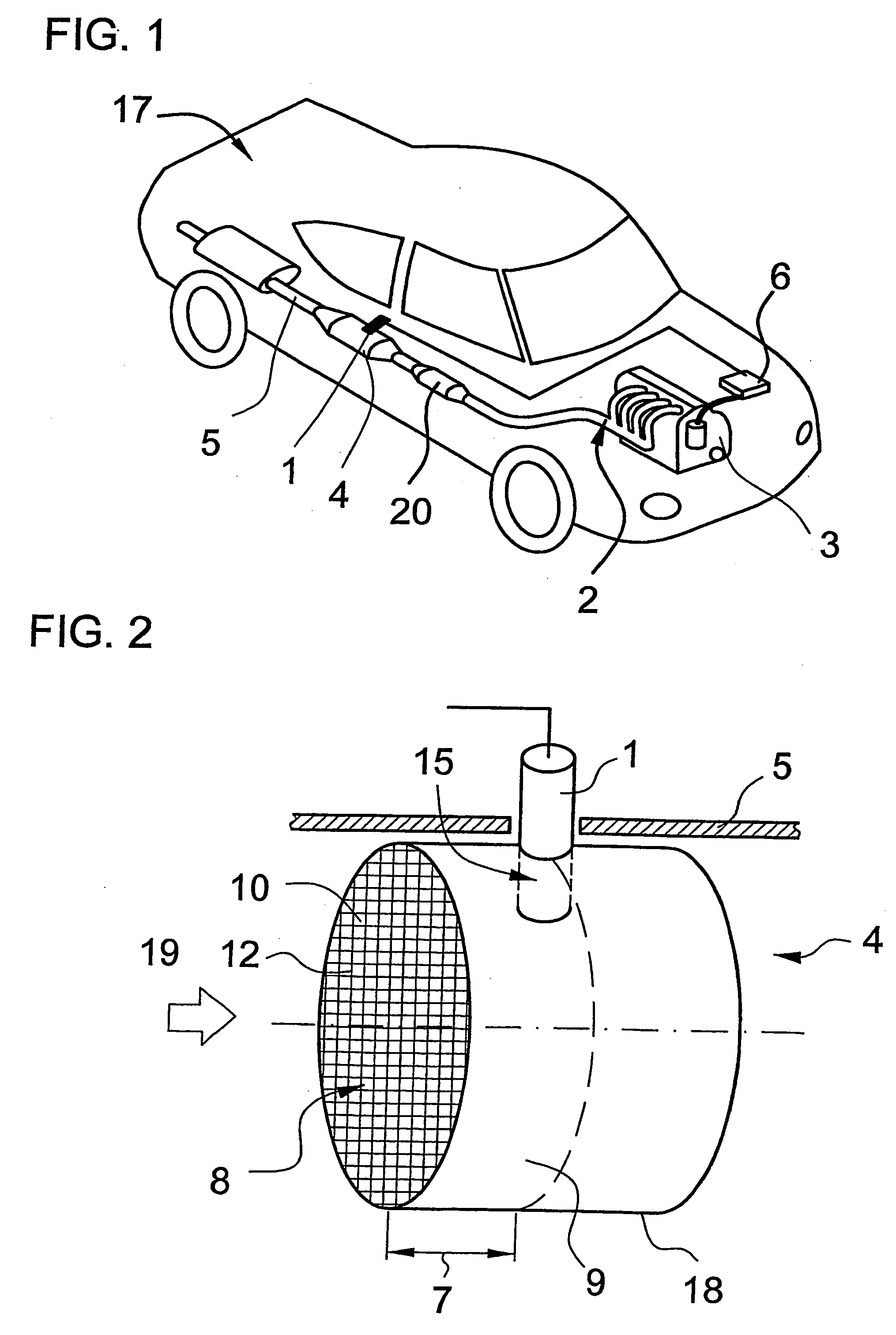
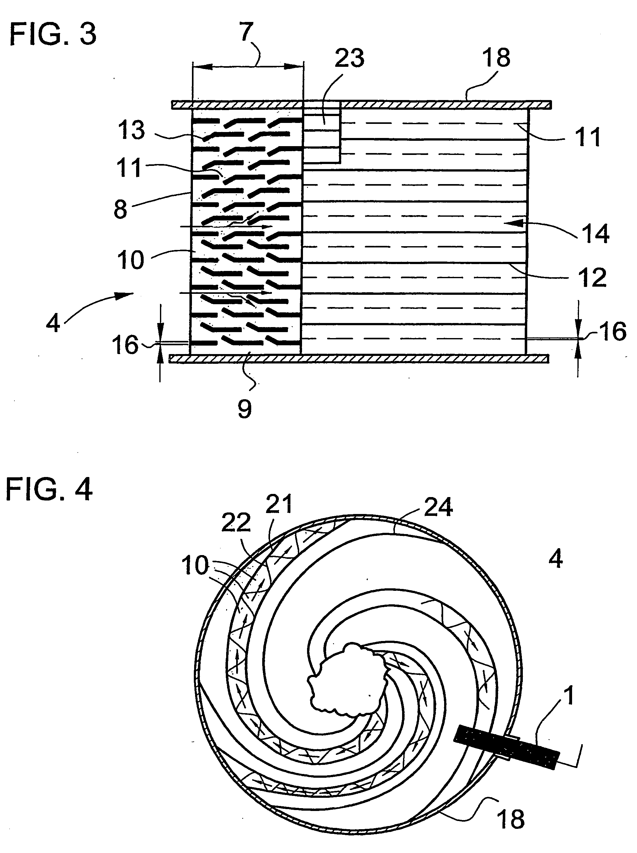
[0059] Referring now to the figures of the drawings in detail and first, particularly, to FIG. 1 thereof, there is seen a diagrammatic and perspective view of a vehicle 17 with an internal combustion engine 3 and an associated exhaust gas system 2. In particular, diesel and spark ignition engines can be provided as the internal combustion engine 3. The exhaust gas which is generated through the use of the internal combustion engine 3 is output into the surroundings through an exhaust gas line 5. For this purpose, the exhaust gas is brought into contact with exhaust gas treatment devices such as, for example, catalytic converters, adsorbers, particle traps etc., with pollutants in the exhaust gas being at least partially converted into at least less noxious components.

[0060] In FIG. 1, the exhaust gas firstly flows through a mixer 20 before it is fed to a catalytic converter 4. The catalytic converter 4 is equipped with a control probe 1 for controlling a fuel mixture or for perform...


PUM


Abstract

A method for controlling a fuel mixture in an exhaust gas system of a mobile internal combustion engine having at least one catalytic converter in an exhaust gas line, includes carrying out the control with an individual control probe in the interior of the at least one catalytic converter. An exhaust gas system and a vehicle having the exhaust gas system, are also provided.

Description

CROSS-REFERENCE TO RELATED APPLICATIONS [0001] This is a continuing application, under 35 U.S.C. §120, of copending International Patent Application PCT / EP2005 / 005968, filed Jun. 3, 2005, which designated the United States; this application also claims the priority, under 35 U.S.C. §119, of German Patent Application DE 10 2004 027 907.1, filed Jun. 9, 2004; the prior applications are herewith incorporated by reference in their entirety.BACKGROUND OF THE INVENTION [0002] Field of the Invention [0003] The invention relates to a method for controlling a fuel mixture through the use of a control probe in the exhaust gas system of a mobile internal combustion engine. Furthermore, an exhaust gas system including a mobile internal combustion engine and a vehicle having the exhaust gas system, are also proposed. The preferred field of use of such exhaust gas systems or methods is the automobile sector. [0004] It is known to use sensors and / or probes in exhaust gas systems of mobile internal...

Claims


Application Information

Patent Timeline
Patent Type & Authority Applications(United States)
IPC IPC(8): F01N3/00F01N3/28F01N13/00F02D41/14
CPCF01N3/2821F01N3/2882F01N2560/02F02D41/1438F02D41/1441F02D41/1494F01N13/009F01N13/0097Y02A50/20F01N11/00F02D41/14G01N27/407
Inventor BRUCK, ROLF
Owner EMITEC GESELLSCHAFT FUR EMISSIONSTECHNOLOGIE MBH
Why Eureka
Try Eureka