Vibration suppressing cutting tool

a cutting tool and vibration suppression technology, applied in the field of cutting tools, can solve the problems of increasing high machining cost, vibration suppressing tools, etc., and achieve the effect of suppressing chattering, reducing the size of the vibration-piece and the pocket, and reducing the possibility of chattering

Active Publication Date: 2007-04-26
SUMITOMO ELECTRIC HARDMETAL CORP
View PDF13 Cites 26 Cited by
  • Summary
  • Abstract
  • Description
  • Claims
  • Application Information

AI Technical Summary

Benefits of technology

[0027] When the holder vibrates, the vibration suppressing piece received in the pocket is vibrated by inertia, thus directly knocking the inner wall of the pocket. At this time, the vibration suppressing piece vibrates in reverse phase to the holder, so that the vibration of the holder is canceled by the vibration of the vibration suppressing piece. Chattering of the holder thus decreases. According to the present invention, the vibration suppressing piece knocks the pocket along its surface, along a plurality of lines, or on a plurality of points. Thus, the load of the vibration suppressing piece disperses to a wide range of the inner wall of the pocket, thus making it possible to substantially suppress chattering.
[0028] By orienting the pocket such that its wall surfaces against which the vibration suppressing piece knocks are perpendicular to the direction of vibration of the holder during cutting, energy from the vibration suppressing piece (energy that serves to cancel vibration of the holder) is transmitted to the shank with a minimum loss, so that it is possible to reduce the size of the vibration-piece and the pocket. This minimizes the reduction in the rigidity of the shank due to the presence of the pocket, thus making it possible to more effectively suppress chattering.
[0029] According to the present invention, because the pocket can be formed from one side of the holder, the tool can be manufactured easily at a significantly l...

Problems solved by technology

This increases the possibility of chattering.
Thus, many of the conventional vibration suppressing tools are boring tools.
In the vibration suppressing cutting tools of Patent documents 1 to 3, because the damper is inserted in the deep hole formed in the shank, the hole has to be formed by e.g. a gun drill especially if the tool is an inner diameter machining tool, of which the shank is long and small in diameter, so that the machining cost is high.
Such a large hollow portion lowers the rigidity of the holder.
Further, the structure is complicated, which also pushes up the cost.
Because these holders are complicated in structure, the diameter of the shank is restricted (so that the diameter of the bore that can machined is also restricted in the case of inner diameter machining).
This means that in order to sufficiently damp vibration, the cutting conditions are restricted.
But such alloys are expensive and formability of these ...

Method used


Image

  • Vibration suppressing cutting tool
  • Vibration suppressing cutting tool
  • Vibration suppressing cutting tool

Examples


embodiment 1

[0090] First, the vibration suppressing tool shown in FIG. 6 is a boring tool which includes a holder 1. A throwaway insert 7 is detachably clamped to the front end of the holder 1 by a clamp means 8. A hole as a pocket 4 is formed in the shank 2 of the holder 1 by e.g. electrical discharge machining so as to extend through the shank 2 from one side thereof to the other side. The pocket 4 is located offset from the axial center of the holder 1 toward its front end. A rectangular parallelepiped vibration suppressing piece 5 made of cemented carbide having a specific gravity of 15.1 is received in the pocket 5. Both open ends of the pocket 4 are closed by lid members 6 to prevent the vibration suppressing pieces 5 from coming out of the pocket 4. The pocket 4 has a rectangular cross-section and includes walls 4a and 4b parallel to each other. The shank 2 of the holder 1 shown has a circular cross-section. But the present invention is applicable to a shank having a polygonal cross-sect...

embodiment 2

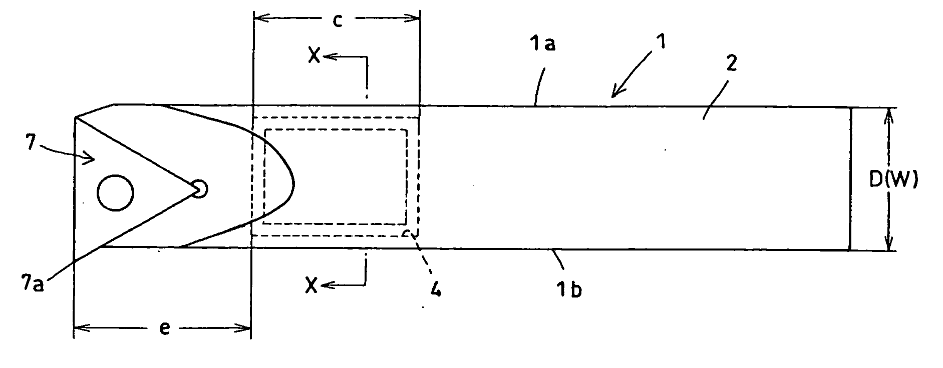
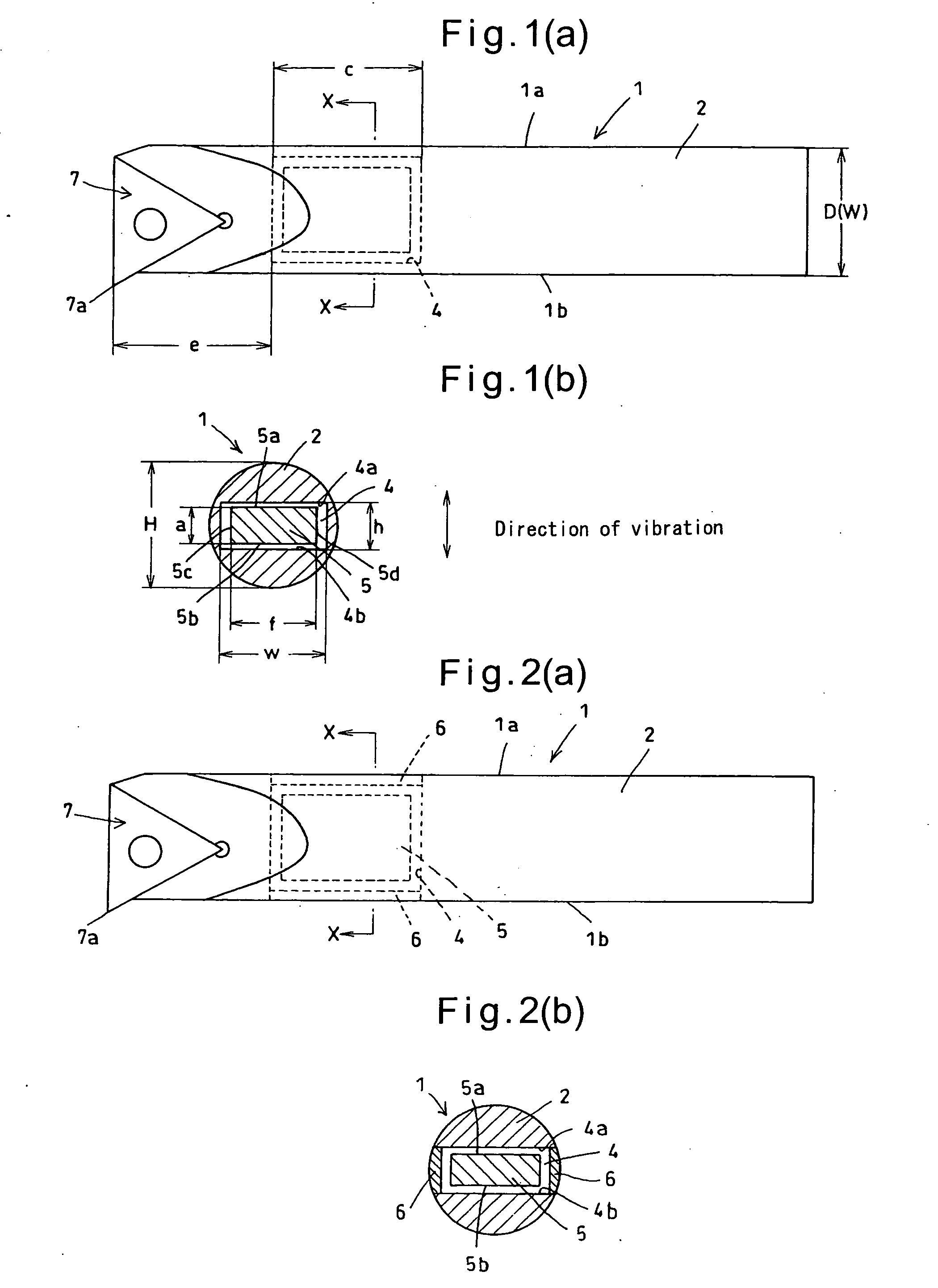
[0098] This embodiment, shown in FIG. 9, is preferable when higher machining accuracy is required. While the tool of FIG. 6 can more effectively suppress chattering by increasing the size of the vibration suppressing piece 5, the shank tends to be low in rigidity because the pocket 4 extends through the shank, so that the machining accuracy tends to be low. The vibration suppressing cutting tool of FIG. 9 is free of this problem.

[0099] The pocket 4 of the vibration suppressing cutting tool of FIG. 9 is formed by an end mill from a side 1a of the shank that is opposite to the side 1b of the shank where the cutting edge 7a is located. Complementary to the contour of the end mill, the pocket 4 has arcuate surfaces at both ends thereof. In order to keep high rigidity of the holder 1, the pocket 4 is a blind hole having a closed end wall having a thickness of about 2 mm on the side 1b of the shank where the cutting edge 7a is located. The opening of the pocket 4 on the side 1a is closed...

embodiment 3

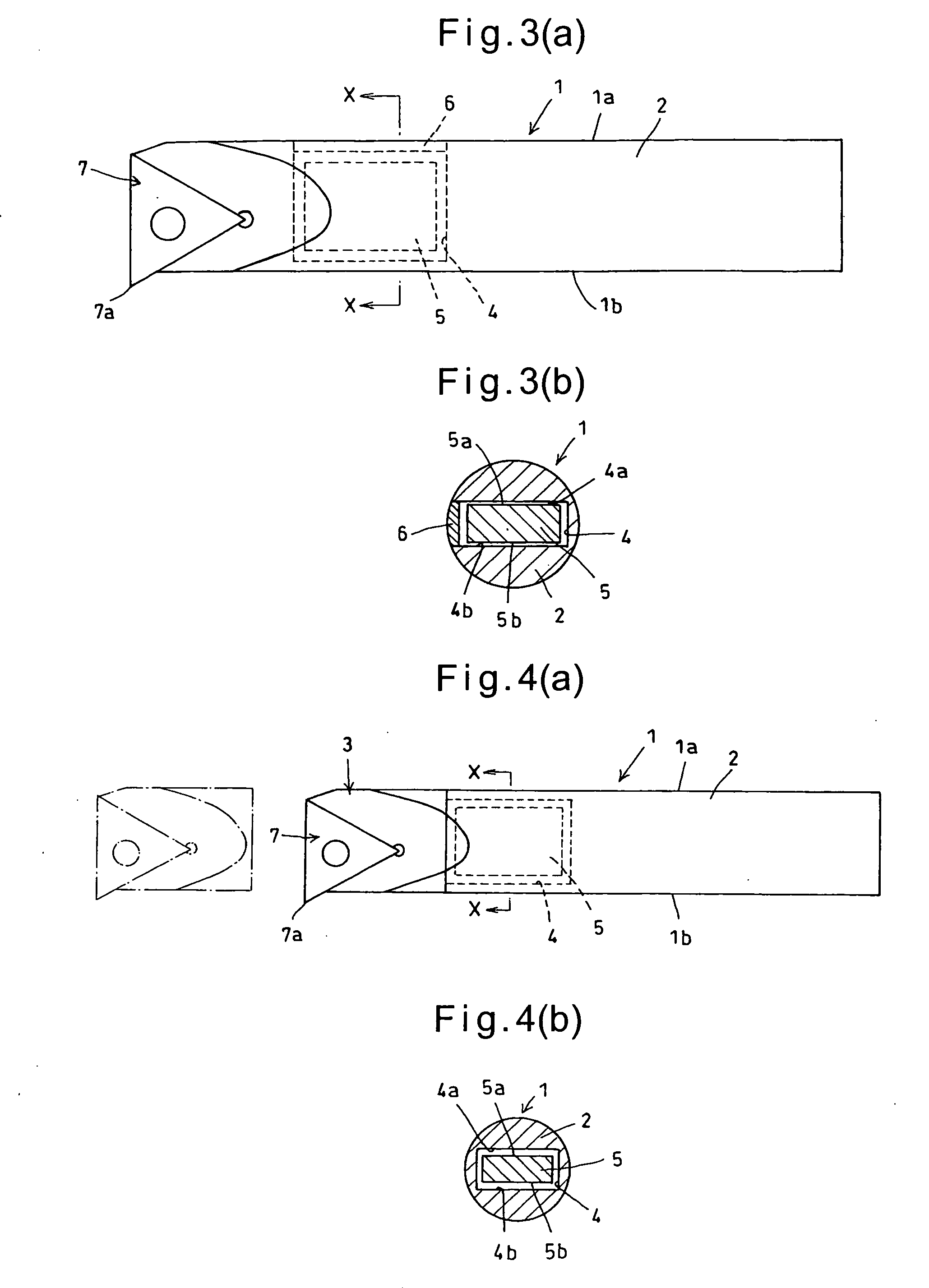
[0109]FIG. 14 shows still another embodiment. The holder 1 of the vibration suppressing cutting tool of FIG. 14 comprises a shank 2 and a head 3 that are formed separately from each other and joined together. The head 3 may be undetachably joined to the shank 2, or may be detachably connected to the shank 2 so that only the head 3 is replaceable if the head 3 is broken.

[0110] In this embodiment, the pocket 4 opens at the front end of the shank 2. By joining the head 3 to the shank 2 with the vibration suppressing piece 5 received in the pocket 4, the head 5 serves as a lid for closing the opening of the pocket 4. This eliminates the need for a separate lid. If the pocket 4 is formed by electrical discharge machining, the shank 2 can be made of cemented carbide, so that it is possible to increase the rigidity of the tool and thus dramatically suppress chattering.


PUM

PropertyMeasurementUnit
Lengthaaaaaaaaaa
Fractionaaaaaaaaaa
Fractionaaaaaaaaaa

Abstract

An object is to provide a vibration suppressing cutting tool which is inexpensive and can damp chattering extremely effectively, and which is simple in structure and is applicable to a wide variety of machining diameters and cutting conditions.
The shank 2 of the holder 1 is formed with a pocket 4. In the pocket 4, a vibration suppressing piece 5 is received so as to be movable relative to the holder 1 and not protrudable from the pocket 4. Under kinetic energy from the holder during cutting, the vibration suppressing piece 5 alternately knocks against a pair of opposed inner wall surfaces 4a and 4b of the pocket along its surface, along a plurality of lines or on a plurality of points when the holder vibrates during cutting, thereby damping vibrations of the holder.

Description

TECHNICAL FIELD [0001] This invention relates generally to a cutting tool which has to be kept free of mainly chattering, and particularly a vibration suppressing cutting tool which is simple in structure and inexpensive, and which includes means for effectively suppressing chattering. BACKGROUND ART [0002] It is well-known to mount a damper in the holder to suppress chattering utilizing inertia. Particularly in the case of inner diameter machining boring tools, because the size of the holder is restricted by the bore diameter of the workpiece, its protrusion has to be increased while reducing the diameter of the shank. This increases the possibility of chattering. Thus, many of the conventional vibration suppressing tools are boring tools. The following description is therefore mainly made with reference to boring tools. [0003] For example, in Patent document 1, a method shown in FIG. 5 is disclosed. In this method, a hole 21 is formed in the holder 1 from its rear end, a damper 22...

Claims


Application Information

Patent Timeline
IPC IPC(8): B23B47/00B23B27/00B23B29/02
CPCB23B27/002Y10T408/76Y10T82/2585B23B29/022B23B27/00B23B29/02
Inventor MURAKAMI, DAISUKEUEDA, MASANOBUKASHIMA, KAZUHIKOOKIDA, JUNYAKIMURA, NORIHIDE
Owner SUMITOMO ELECTRIC HARDMETAL CORP
Why Eureka
Try Eureka