
Method To Determine The Depth-Of-Interaction Function For PET Detectors

a technology of depth-of-interaction and pet detector, which is applied in the field of positron emission tomography (pet) imaging, can solve the problems of poor spatial resolution, current pet detectors can only detect two-dimensional signals, and pet has faced a fundamental technical challenge in image resolution

Inactive Publication Date: 2007-04-26
THE RES FOUND OF STATE UNIV OF NEW YORK
View PDF32 Cites 8 Cited by
  • Summary
  • Abstract
  • Description
  • Claims
  • Application Information

AI Technical Summary

Benefits of technology

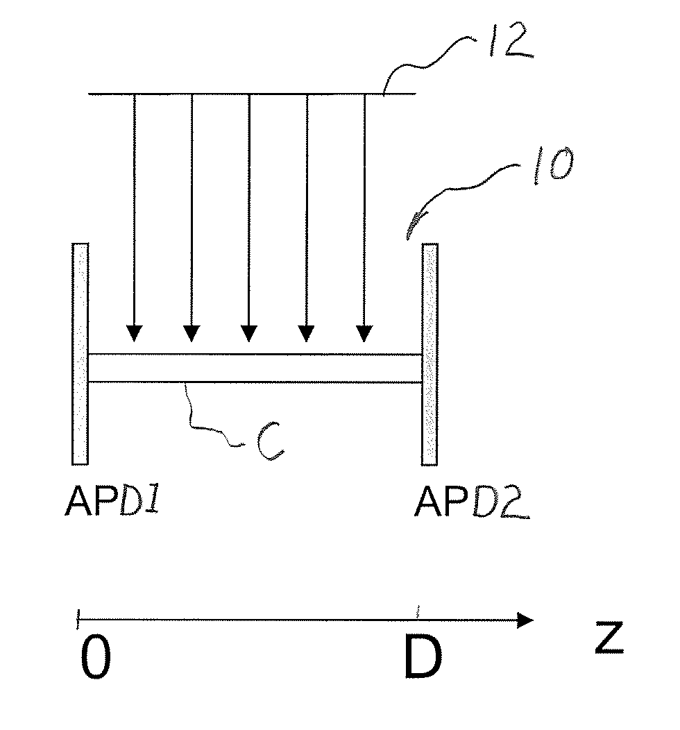
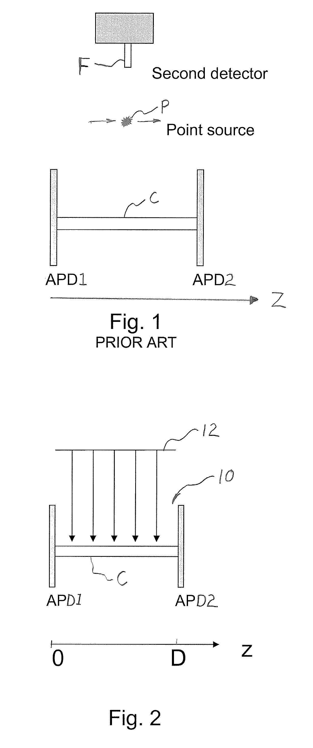
[0009] It is an object of the present invention to provide an improved method for calibrating three-dimensional PET detectors of a type having a scintillation crystal and first and second photosensitive detectors arranged one at each opposite end face of the crystal for detecting scintillation interactions within the crystal. More specifically, it is an object of the present invention to provide a method for determining a DOI function of a PET detector that is significantly easier and faster to execute, and yields more accurate results, than prior art methods. It is ultimately a goal of the present invention to provide a calibration method that is suitable for practical use in the fields of medical and research imaging.
[0011] The method of the present invention avoids the need for an additional calibration detector and source that must be aligned and moved together in steps along the depth axis of the crystal to make many different measurements. Thus, the method of the present invention is faster and easier than prior methods. In addition, the method of the present invention yields more accurate calibration results than prior methods.

Problems solved by technology

However, PET has faced a fundamental technical challenge with regard to image resolution.
The main technical problem is that current PET detectors can only detect two-dimensional signals (an X-Y location), and the Z location coordinate is an approximation based on the location of the detector scintillation crystal.
This situation results in poor spatial resolution associated with parallax error due to the crystal penetration by energetic gamma photons.
It is a recognized problem that spatial resolution suffers near the radial edges of the field-of-view (FOV), resulting in a lack of spatial resolution uniformity over the entire FOV.
Although this new design has made significant progress, its widespread adoption may take a few more years due mainly to cost issues associated with photon sensors.
With this new PET detector design, there is one major technical challenge: it needs an efficient and accurate calibration method to determine the response function of the three-dimensional detector.
There are several drawbacks with this method, including that it requires complicated experimental setup with an extra detector and coincidence process to allocate the DOI position; the measurement has to be taken at different DOI positions along the crystal, which requires demanding detector / source alignment and movement and lengthy time to complete; and it is potentially prone to significant measurement error due to the setup itself and size limitations of the second detector F. Moreover, the current method is simply not practical to measure the DOI functions for multiple crystals inside an array of crystals.
At present, there is no effective calibration method for such three-dimensional PET detectors.
The current method described in the preceding paragraph requires a movable radiation source to be accurately aligned with the detector, which is a complicated setting, and cannot be applied to a practical detector since the inner crystals in an array cannot be calibrated.
The calibration process is very long and tedious, and is not useful for practical purposes.
In summary, the current method of determining a DOI function requires complicated settings for laboratory bench-top testing, and still cannot be applied to any practical detectors, or is too coarse or unstable to be used for accurate calibration required by medical industry standards.

Method used


Image

  • Method To Determine The Depth-Of-Interaction Function For PET Detectors
  • Method To Determine The Depth-Of-Interaction Function For PET Detectors
  • Method To Determine The Depth-Of-Interaction Function For PET Detectors

Examples


Embodiment Construction

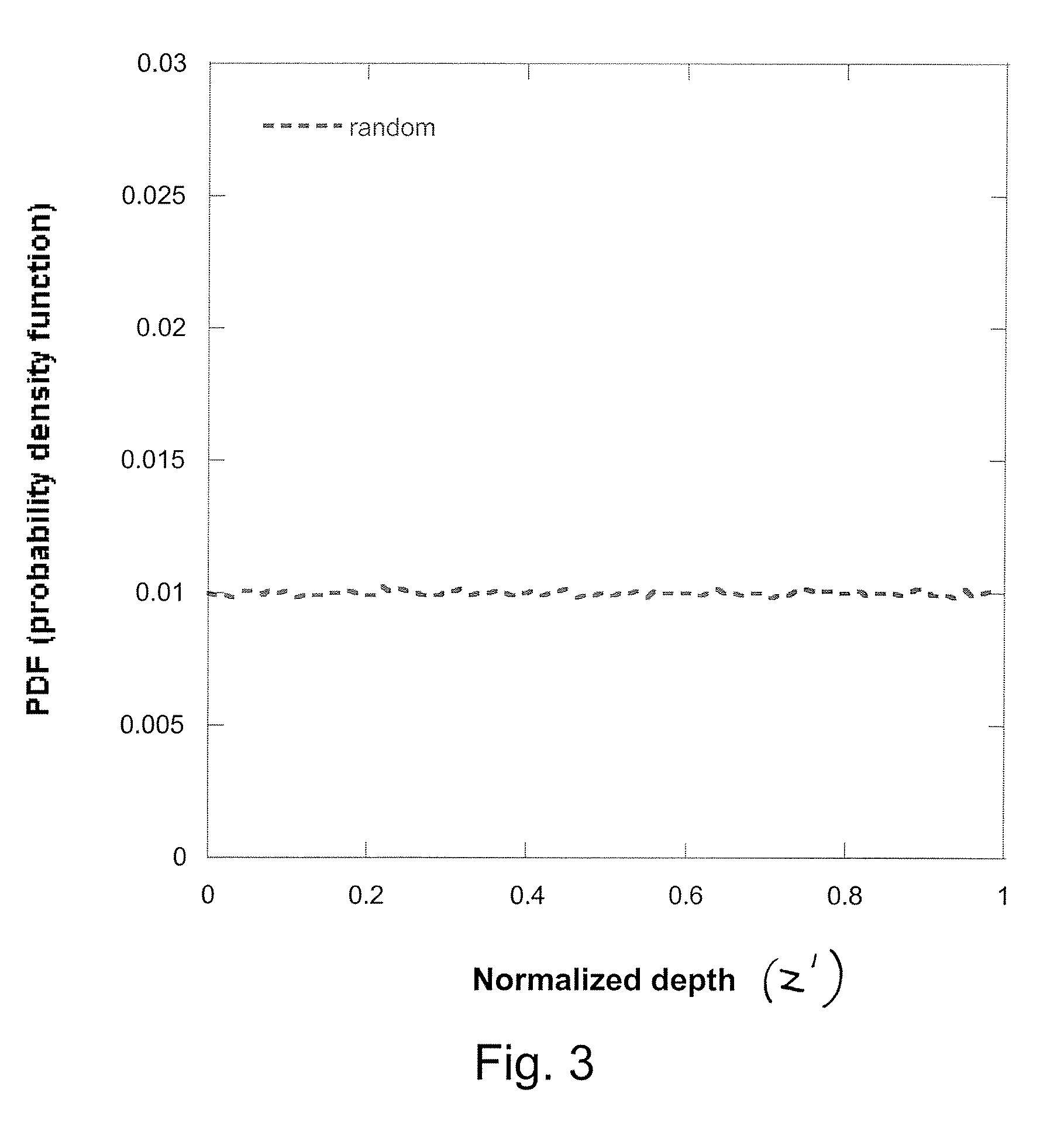
[0022] This invention provides a new and innovative method for calibrating three-dimensional PET detectors by applying probability techniques to the problem of calibration. The method is simple, efficient, and accurate, and can be used for the development, installation, and diagnostic use of three-dimensional PET detectors. The method provides a calibration process involving only a small number of settings which can be easily made or automated if desired. Consequently, the method of the present invention will be attractive to manufacturers and users of PET imaging equipment. While the present invention is described herein with reference to detection of gamma ray interactions, it applies equally well to x-ray interactions.

[0023] The present invention requires only a stationary uniform radiation source which can be very easily set; it does not require any mechanism for moving the source or an additional detector as in other methods. Thus, the calibration method of the present inventi...


PUM


Abstract

A three-dimensional PET detector of a type having a scintillation crystal and first and second photosensitive detectors arranged one at each opposite end face of the crystal for detecting scintillation interactions within the crystal is calibrated to determine a depth-of-interaction (DOI) function thereof by irradiating the crystal to cause a predetermined distribution of interactions along a depth axis of the crystal, and applying probability theory to signal data collected by the two photosensitive detectors. The method provides a DOI function that indicates DOI position as a function of a signal ratio R obtained from the signal data.

Description

CROSS-REFERENCE TO RELATED APPLICATIONS [0001] The present application claims benefit of U.S. Provisional Patent Application No. 60 / 728,488 filed Oct. 20, 2005, the entire disclosure of which is hereby incorporated herein by reference.FIELD OF THE INVENTION [0002] The invention relates generally to the field of Positron Emission Tomography (PET) imaging and other radiation detections. BACKGROUND OF THE INVENTION [0003] Positron Emission Tomography (PET) has become a main stream medical imaging technique for applications in oncology, cardiology, neurology, and other medical disciplines. In a PET imaging device, pairs of gamma photons resulting from a positron-electron annihilations within a patient are detected in detectors surrounding the patient. The photons in a given pair travel in opposite directions defining a line of response (LOR), and two detectors on opposite sides of the patient generate signals that represent the respective locations of two points along the LOR. The signa...

Claims


Application Information

Patent Timeline
IPC IPC(8): G01T1/20
CPCG01T1/2018A61B6/037G01T1/2985G01T1/20187
Inventor SHAO, YIPING
Owner THE RES FOUND OF STATE UNIV OF NEW YORK
Learn More