Integrated battery unit for electric vehicles

Active Publication Date: 2007-04-26
WEBASTO CHARGING SYST INC
View PDF24 Cites 26 Cited by
  • Summary
  • Abstract
  • Description
  • Claims
  • Application Information

AI Technical Summary

Benefits of technology

[0017] According to an embodiment of the invention, the thermal management and ventilation and motor controller isolation systems may be housed in a single integrated battery unit (IBU), which can be easily installed in existing electric vehicles, without requiring any substantial modifications to be made to the vehicle. A charge port that is easily accessible by an operator, and/or a watering solenoid valve may also be inte

Problems solved by technology

While fast charging improves operational efficiencies, its use generates temperatures and thermal gradients in a battery pack, which if not properly controlled contribute to degraded performance and a shortened lifespan of the battery pack. FIG. 2 shows a graph of the effective internal resistance and heat generation observed in a typical thirty-six-volt industrial battery at different inrush currents and states of charge (SOC).
This excessive heating results in significantly higher temperatures in the fast charged battery pack.
This substantially enclosed configuration does not allow for any significant cooling paths, especially for cells disposed in the center of the pack.
Because the center cells of a battery pack endure higher temperatures than cells forming the periphery of the battery pack, the center cells are plagued with diminished performance and are even prone to fail more often compared to the peripheral cells. FIG. 3A shows cell voltages of a battery pack of eighteen cells (which are arranged as shown in FIG. 3B) during discharge at 20% SOC, before and after equalization (EQ) of a battery pack that has undergone fast charging during a life cycle test.
As the foregoing demonstrates, without adequate cooling a battery pack is beset with reduced capacity and run time.
Cell-to-cell imbalances can also lead to over-discharging during use and overcharging during recharging, both of which further affect the performance and lifespan of the battery pack.
The operational efficiencies gained by fast charging introduce additional problems beyond that of just thermal and ventilation management.
For

Method used


Image

  • Integrated battery unit for electric vehicles
  • Integrated battery unit for electric vehicles
  • Integrated battery unit for electric vehicles

Examples


Example

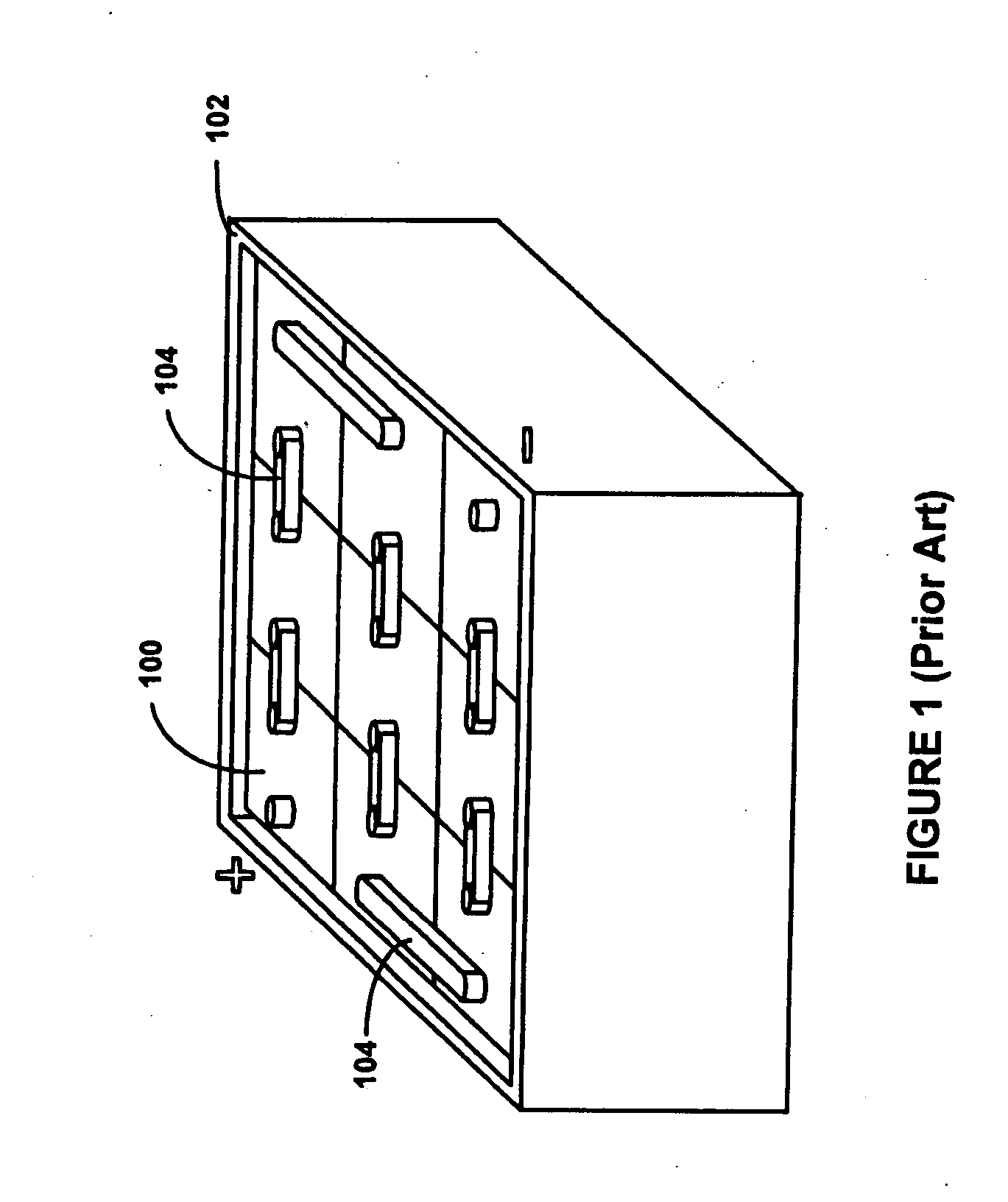
[0042] According to a first embodiment of the present invention, a thermal and ventilation management system for a battery pack is disclosed. The system includes one or more “fan-modules” that are inserted between cells of a battery pack, which may be housed in a battery pack case (i.e., “tray”). The battery pack may be a custom-made battery pack or may be a standard battery pack, as shown, for example, in FIG. 1.

[0043]FIGS. 5A-5D are side, front, top and isometric views, respectively, of a fan module 500 for use in a battery pack, according to an embodiment of the present invention. An air inlet port 502 is configured to receive fresh air from the environment. A first filter 504 (e.g. a mesh screen) prevents dirt and other particulate matter from entering the fan module 500 through the air inlet port 502. An air outlet port 506 is configured to eject heated air out into the environment and away from the battery pack and battery pack case. As shown in FIGS. 5C and 5D, a second filt...


PUM


Abstract

Methods of and apparatus for removing heat generated by cells of a battery pack. The method and apparatus may employ one or more fan modules disposed between or next to cells of the battery pack, or one or more fans directly mounted to the battery pack or battery pack case housing the cells. Further, a motor controller isolation system operates to electricity isolate the motor controller of the electric vehicle when the battery pack is being charged. The motor controller isolation system may be integrated with the integrated battery pack and thermal and ventilation system. The integrated system, or “integrated battery unit (IBU),” is preferably manufactured in a manner that requires no, modifications to the electric vehicle in which the IBU is installed.

Description

FIELD OF THE INVENTION [0001] The present invention relates to electric vehicles. More specifically, the present invention relates to adapting electric vehicles for fast charging technology, and to providing thermal and ventilation management for battery packs used in electric vehicles. BACKGROUND OF THE INVENTION [0002] Recreational and industrial vehicles are prevalent in today's world. Examples include golf carts, forklifts, and airport transport and luggage handling carts. Because electric vehicles create less pollution than internal combustion (i.e., gasoline and diesel powered) vehicles, they are an environmentally friendly, and increasingly acceptable, alternative. [0003] As shown in FIG. 1, electric vehicles are typically powered by a battery pack comprised of a plurality of rechargeable batteries (or “cells”) 100. The battery pack cells 100 are housed in a battery pack case (or “tray”) 102. The cells 100 are usually connected in series by way of electrical connectors 104. T...

Claims


Application Information

Patent Timeline
IPC IPC(8): H02J7/04H01M50/204H01M50/249
CPCH01M2/1077H01M10/46H01M10/5004H01M10/5016H01M10/502H01M10/5059H01M10/5067Y02E60/12H01M10/625H01M10/63H01M10/6563H01M10/6557H01M10/613B60L53/11B60L58/26B60L53/18Y02T10/70Y02T10/7072Y02T90/14Y02E60/10H01M50/204H01M50/249B60L3/0069B66F9/07595H01M2220/20
Inventor DICKINSON, BLAKE E.HAYASHIGAWA, LARRY
Owner WEBASTO CHARGING SYST INC
Why Eureka
Try Eureka