Coding distortion removal method, video encoding method, video decoding method, and apparatus and program for the same

a technology of coding distortion and removal method, which is applied in the field of coding distortion removal method, video encoding method, video decoding method, and apparatus and program for the same, can solve the problems of inability to accurately distinguish image signals, high amount of data processed per unit time, and complex processing and implementation. to achieve the effect of efficient removal of coding distortion

Inactive Publication Date: 2007-04-26
GK BRIDGE 1
View PDF21 Cites 74 Cited by
  • Summary
  • Abstract
  • Description
  • Claims
  • Application Information

AI Technical Summary

Benefits of technology

[0042] By thus using plural images deblocked by at least two methods as reference images and sequentially selecting the appropriate one for reference, the picture obtained by efficiently removing coding distortion from an image signal containing coding distortion can be used as the r...

Problems solved by technology

The conventional coding distortion removal methods described above are particularly effective at removing coding distortion, but the process is extremely complex and implementation difficult.
A further problem is that the amount of data processed per unit time is high.
Furthermore, no matter how effective the coding distortion removal method, it is impossible to accurately distinguish image signals and coding distort...

Method used


Image

  • Coding distortion removal method, video encoding method, video decoding method, and apparatus and program for the same
  • Coding distortion removal method, video encoding method, video decoding method, and apparatus and program for the same
  • Coding distortion removal method, video encoding method, video decoding method, and apparatus and program for the same

Examples


embodiment 1

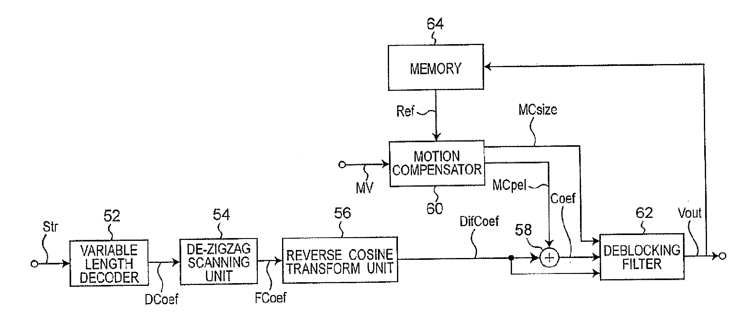
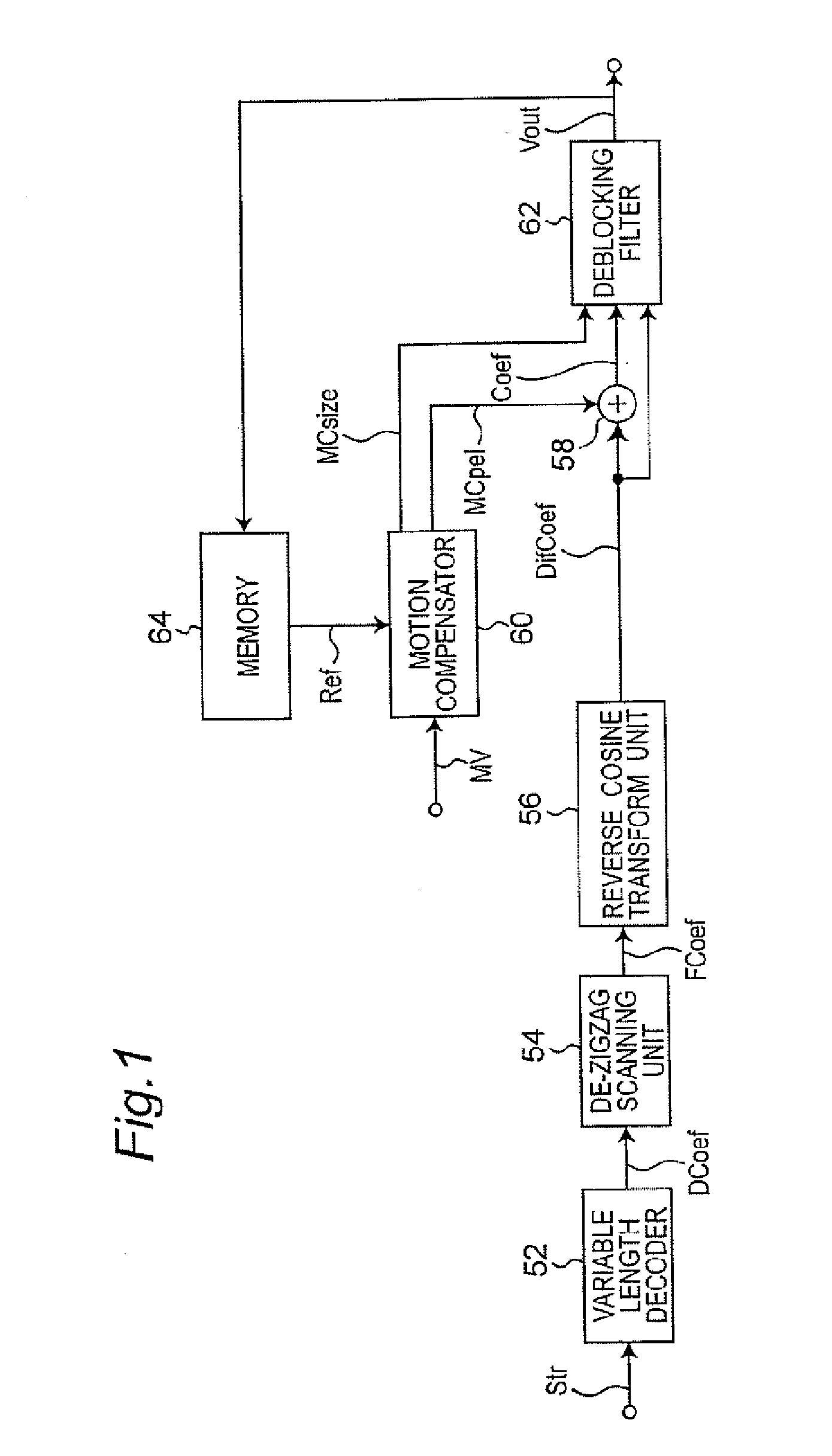
[0100] In the block diagram of a video decoding apparatus using a video decoding method, variable length decoder 52 variable length decodes encoded signal Str and outputs frequency code component DCoef. De-zigzag scanning unit 54 rearranges the frequency components of the frequency code component DCoef in two-dimensional blocks, and outputs frequency component FCoef, the block unit frequency components. The reverse cosine transform unit 56 applies dequantization and reverse DCT operations to frequency component FCoef, and outputs difference image DifCoef.

[0101] Motion compensator 60 outputs the pixel at the position indicated by externally input motion vector MV from the reference image Ref accumulated in memory 64 as motion compensated image MCpel and outputs motion compensation block size MCsize denoting the size of the motion compensation block. Adder 58 adds difference image DifCoef and motion compensated image MCpel to output reconstructed image Coef.

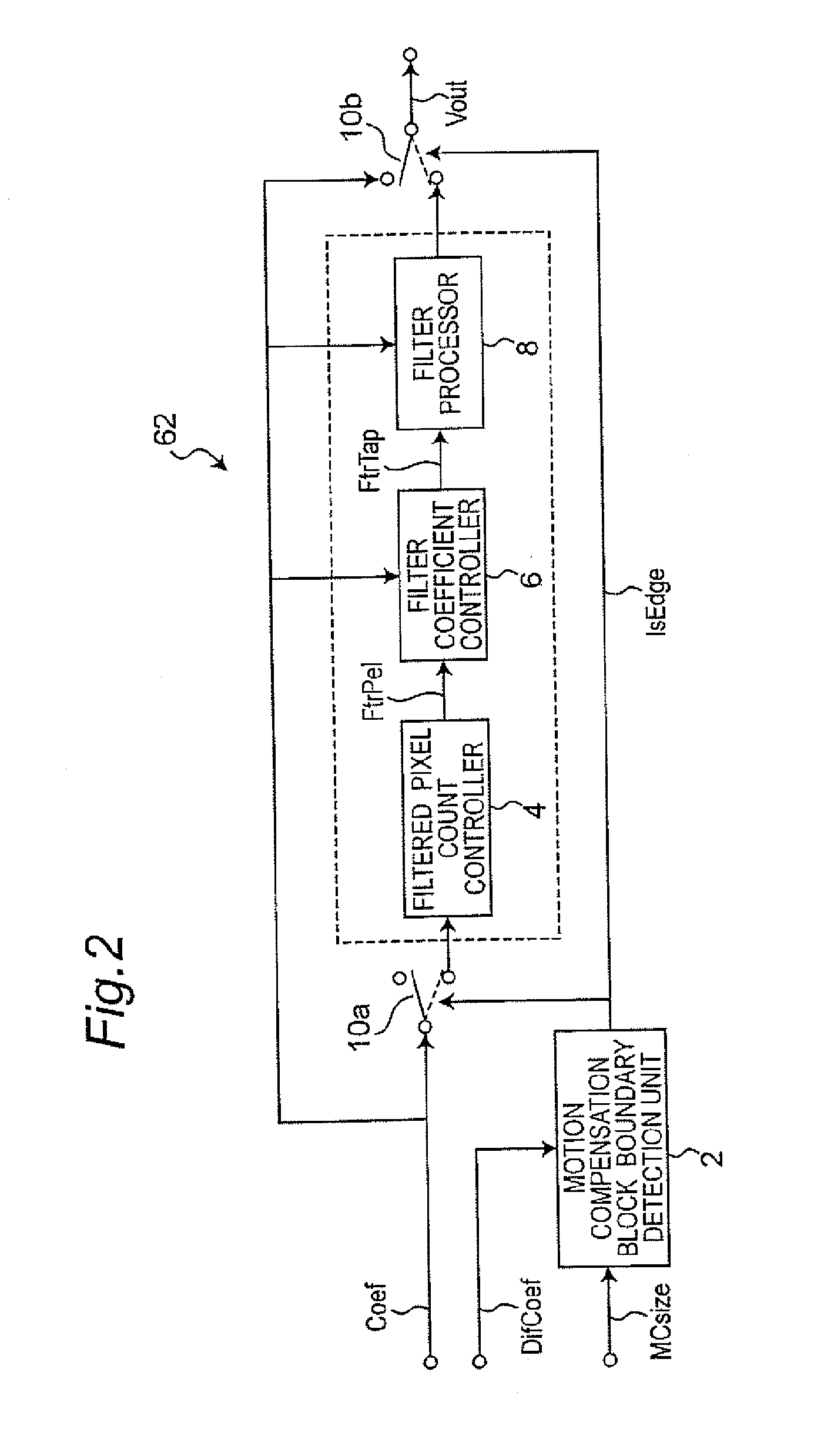
[0102] Deblocking filter ...

embodiment 2

[0114] A specific process whereby coding distortion removal can be easily achieved is described in this embodiment of the invention with reference to the flow chart in FIG. 4 of a coding distortion removal method according to the present invention.

[0115] It is first determined in step S18 whether the target block is a coding distortion removal block. If it is, control advances to step S19. If it is not, control advances to step S24.

[0116] An appropriate coding distortion removal filter is selected in step S19, coding distortion removal processing is applied using the selected filter in step S20, and the target pixel is changed to the next unprocessed pixel in the block in step S21. If there are no unprocessed pixels in the block (step S22 returns no) control advances to step S24. If there is an unprocessed pixel (step S22 returns yes), control loops back to step S19 and the process repeats.

[0117] Step S24 detects if there is another unprocessed block in the picture. If there is, ...

embodiment 3

[0140] This embodiment of the invention describes an encoding apparatus and a decoding apparatus implementing the coding distortion removal method described in another embodiment of the invention.

[0141]FIG. 9 is a block diagram of the encoding apparatus.

[0142] Motion detection unit 30 compares reference image Ref1 and reference image Ref2 output respectively from first memory 38 and second memory 40 with image signal Vin, and detects motion vector MV, that is, the amount of motion in image signal Vin relative to the reference image. It should be noted that information indicating whether prediction error will be less by referencing reference image Ref1 or reference image Ref2 is also included in the motion vector MV and reported to motion compensation unit 32. The motion compensation unit 32 extracts the image at the position indicated by motion vector MV from reference image Ref1 or reference image Ref2, and outputs it as motion compensated image MCpel.

[0143] Subtracter 42 obtain...


PUM


Abstract

Mosaic-shaped block noise occurs when a compressed video signal is reproduced. This block noise is removed, but removing block noise from every block using a deblocking filter imposes a significant load on the deblocking filter. This load is therefore reduced by determining whether coding distortion removal (deblocking) is necessary, and applying a deblocking filter only when needed.

Description

CROSS-REFERENCE TO RELATED APPLICATIONS [0001] This application is a continuation of U.S. patent application Ser. No. 10 / 466,549, filed Jul. 24, 2003 pending, which is a U.S. National Stage Application of PCT / JP02 / 12487, filed Nov. 29, 2002 and which claims the benefit of U.S. Provisional Application No. 60 / 333,763, filed Nov. 29, 2001, U.S. Provisional Application No. 60 / 333,767, filed Nov. 29, 2001, and U.S. Provisional Application No. 60 / 394,312, filed Jul. 9, 2002. This application also claims priority of Japanese Application Nos. 2002-008859, filed Jan. 17, 2002, 2002-110748, filed Apr. 12, 2002, 2002-127101, filed Apr. 26, 2002, and 2002-291264, filed Oct. 3, 2002, the subject matter of which are expressly incorporated herein in their entireties.TECHNICAL FIELD [0002] The present invention relates to a coding distortion removal method for removing coding distortion that occurs when encoding a video signal, an encoding method and a decoding method for increasing the compression...

Claims


Application Information

Patent Timeline
IPC IPC(8): H04N11/04H04B1/66G06T9/00H04N7/26H04N7/50
CPCH04N19/0089H04N19/86H04N19/159H04N19/176H04N19/172H04N19/46H04N19/61H04N19/112H04N19/117H04N19/136H04N19/14H04N19/137H04N19/154H04N19/157H04N19/16H04N19/182H04N19/174H04N19/80H04N19/82H04N19/105G06T5/001H04N19/124H04N19/44
Inventor XUE, ZHONGSHEN, SHENG MEIFOO, TECK WEELEE, CHAK JOOKADONO, SHINYA
Owner GK BRIDGE 1
Why Eureka
Try Eureka