Electric hybrid powertrain system

Inactive Publication Date: 2007-04-26
FORD GLOBAL TECH LLC
View PDF14 Cites 93 Cited by
  • Summary
  • Abstract
  • Description
  • Claims
  • Application Information

AI Technical Summary

Benefits of technology

[0011] It is an objective of the invention to provide a hybrid electric vehicle powertrain that is adapted for improved forward drive gradeability and improved reverse drive performance for a heavy-duty vehicle, such as a utility vehicle or a truck. The powertrain of the invention includes a g

Problems solved by technology

This characteristic of a single ratio powersplit powertrain may limit vehicle applications with which such a powertrain could be used.
Further, a single ratio powersplit powertrain may not be capable of providing required forward

Method used


Image

  • Electric hybrid powertrain system
  • Electric hybrid powertrain system
  • Electric hybrid powertrain system

Examples


Example

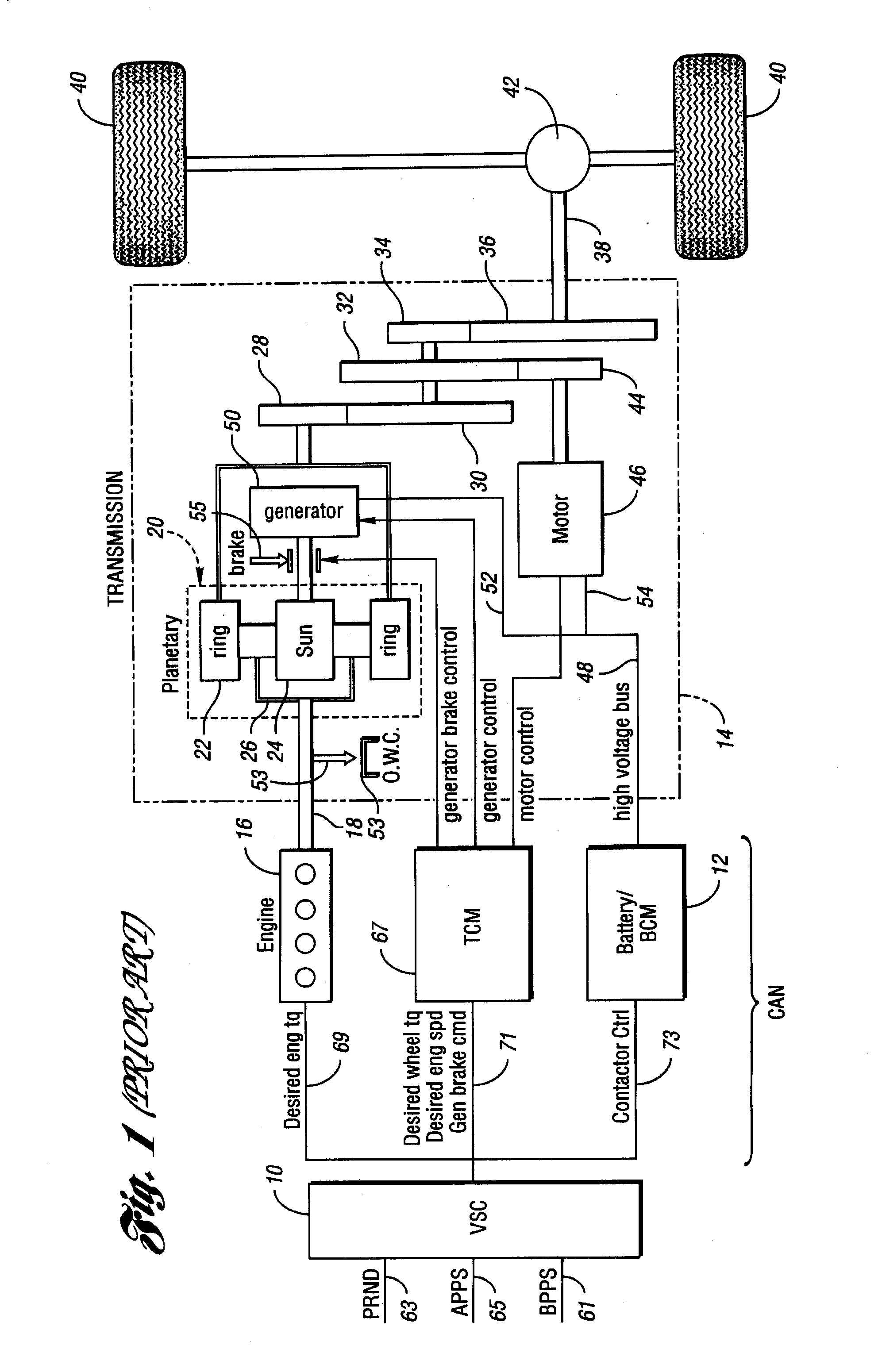
[0045] A known hybrid electric vehicle powertrain is illustrated in FIG. 1. A powertrain of this type is described in the preceding discussion of the background of the invention. The powertrain of FIG. 1 includes a vehicle system controller 10, a battery and battery control module 12, and a transmission control module 67 comprising a so-called control area network (CAN). An engine 16 controlled by the controller 10 distributes torque through torque input shaft 18 to transmission 14.

[0046] The transmission 14 includes a planetary gear unit 20, which comprises a ring gear 22, a sun gear 24, and a planetary carrier assembly 26. The ring gear 22 distributes torque to step ratio gears comprising meshing gear elements 28, 30, 32, 34 and 36. A torque output shaft 38 for the transaxle is drivably connected to vehicle traction wheels 40 through a differential-and-axle mechanism 42.

[0047] Gears 30, 32 and 34 are mounted on a countershaft, the gear 32 engaging a motor-driven gear 44. Electri...


PUM


Abstract

A hybrid electric vehicle powertrain having an engine and an electric motor and generator sub-system, which establish mechanical and electric power flow paths. Multiple-ratio gearing in a power flow path for forward drive enhances vehicle traction torque for heavy-duty vehicle applications. Reverse drive performance is enhanced by torque multiplying gearing in a reverse drive power delivery path.

Description

CROSS-REFERENCE TO RELATED APPLICATIONS [0001] This application claims the benefit of U.S. provisional application Ser. No. 60 / 728,675 filed Oct. 20, 2005.BACKGROUND OF THE INVENTION [0002] 1. Field of the Invention [0003] The invention relates to hybrid electric vehicle powertrains with a powersplit operating mode. [0004] 2. Background of the Invention [0005] It is known design practice to provide hybrid electric vehicle powertrains for automotive vehicles wherein power delivery to the vehicle traction wheels takes place through a single ratio powersplit gearing system. An example of a powertrain of this type is disclosed in U.S. Pat. No. 6,994,360, which is assigned to the assignee of the present invention. Another example is disclosed in U.S. Pat. No. 5,791,427. In powertrains of this type, an electric power source comprising a motor-generator, a battery and a traction motor function with an engine power source seamlessly as they deliver torque through a gear system to the vehicl...

Claims


Application Information

Patent Timeline
IPC IPC(8): F16H3/72
CPCB60K1/02B60K6/365B60K6/40B60K6/445B60K6/46B60K6/48B60K6/52B60K6/547B60K17/344F16H3/728F16H2037/0873F16H2200/0034F16H2200/2007F16H2200/2023F16H2200/2041F16H2200/2064Y02T10/6217Y02T10/6221Y02T10/6265Y02T10/90B60L11/123B60L11/14Y02T10/6239Y10S903/917Y10S903/911Y02T10/7077Y02T10/7005B60L50/61B60L50/16Y02T10/62Y02T10/7072Y02T10/70
Inventor SUPINA, JOSEPHKOZAREKAR, SHAILESH
Owner FORD GLOBAL TECH LLC
Why Eureka
Try Eureka