
Color image projection system and method

a projection system and color image technology, applied in the field of two-dimensional projection, can solve the problems of large physical size and power consumption of known projection systems, limited resolution projection of known image projection systems, and impracticality for use in miniature, hand-held, battery-operated applications, etc., to reduce noise, minimize power consumption, and increase the gain of incident beams

Inactive Publication Date: 2007-05-03
MICROVISION
View PDF13 Cites 26 Cited by
  • Summary
  • Abstract
  • Description
  • Claims
  • Application Information

AI Technical Summary

Benefits of technology

[0006] Another object of this invention is to minimize power consumption, cost and complexity in such projection systems by not utilizing green lasers and their associated circuitry.
[0007] Still another object of this invention is to increase the resolution of the color image projected by such systems.
[0008] Yet another object of this invention is to eliminate the use of green lasers in such systems.
[0010] An additional object is to provide a miniature, compact, lightweight, and portable color image projection system useful in many instruments of different form factors. FEATURES OF THE INVENTION
[0013] In the preferred embodiment, the scanner includes a pair of oscillatable scan mirrors for sweeping the composite beam along generally mutually orthogonal directions at different scan rates and at different scan angles. At least one of the scan rates exceeds audible frequencies, for example, over 18 kHz, to reduce noise. At least one of the scan mirrors is driven by an inertial drive to minimize power consumption. The image resolution preferably exceeds one-fourth of VGA quality, but typically equals or exceeds VGA quality. The lasers, scanner, controller and optical assembly preferably occupy a volume of less than seventy cubic centimeters.
[0014] The projection screen includes a collimating lens, for example, a Fresnel lens, for collimating the red, blue and violet beams into parallel light rays; a lenticular lens array having a plurality of lenses for focusing the parallel light rays at a focusing plane at which the light-transmissive plate is located; and a mask having a plurality of apertures operative for transmitting incident red, blue and green beams therethrough, thereby enabling a red, blue and green (RBG) image to be displayed on the screen. To increase the gain of the incident beams on the screen, a plurality of lenslets is provided, one for each aperture of the mask.

Problems solved by technology

However, the known image projection systems project the image with limited resolution, typically less than a fourth of video-graphics-array (VGA) quality of 640×480 pixels.
The physical size and power consumption of the known projection systems are relatively high, thereby rendering them impractical for use in miniature, hand-held, battery-operated applications, due in large part to the use of infrared diode-pumped Nd: YV04 crystal lasers with crystal doublers to generate the green beam, as well as acousto-optical modulators for pulsing the green beam.
Also, the low scan rates of the scan mirrors generate objectionable noise and vibration during use.

Method used


Image

  • Color image projection system and method
  • Color image projection system and method
  • Color image projection system and method

Examples


Embodiment Construction

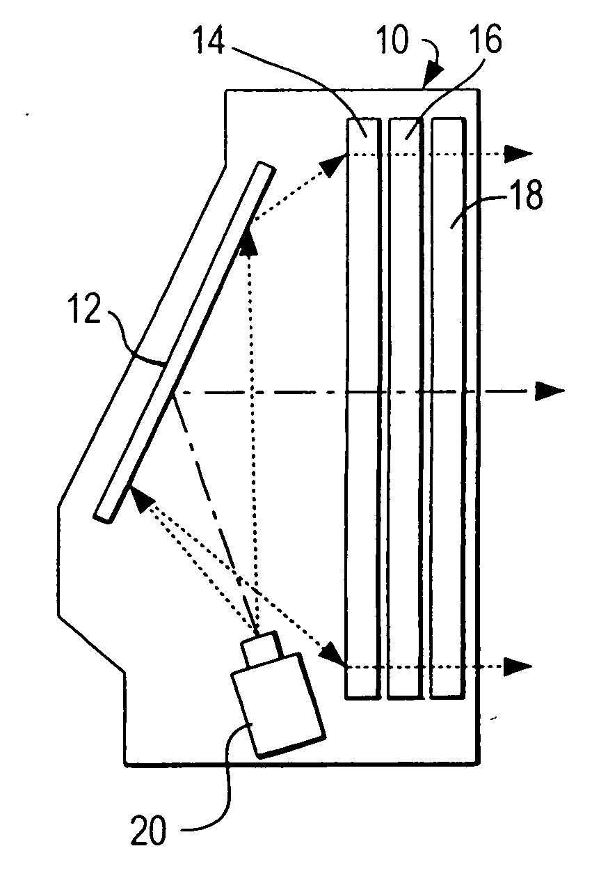
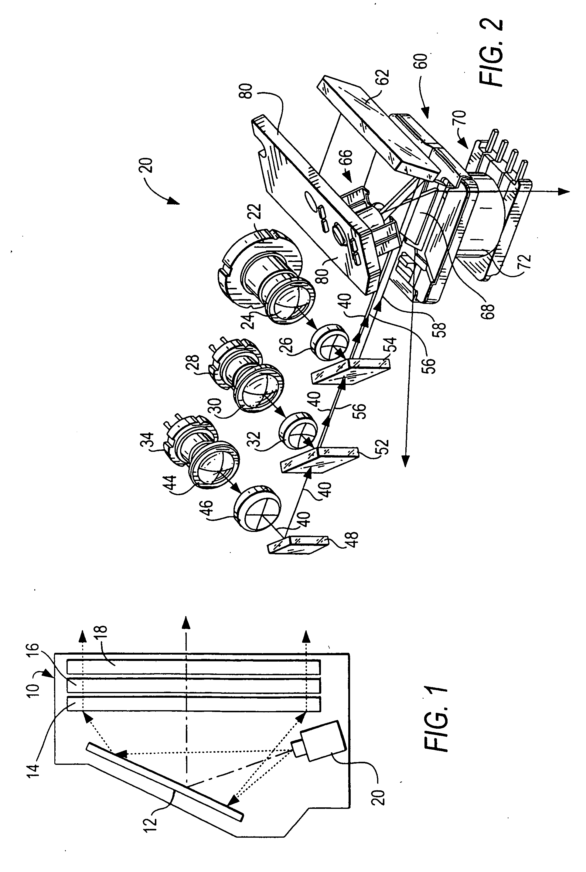
[0028] Reference numeral 10 in FIG. 1 generally identifies a housing in which a lightweight, compact, image projection arrangement 20, as shown in FIG. 2, is mounted and operative for projecting a composite beam onto a stationary rear mirror 12 for reflection therefrom onto a rear projection screen comprising a collimating lens 14, a lenticular lens array 16, and an apertured mask 18, whose structure and function are described below in connection with FIGS. 8-12. An observer in front of the screen sees a two-dimensional, red, blue and green color image thereon, as described below.

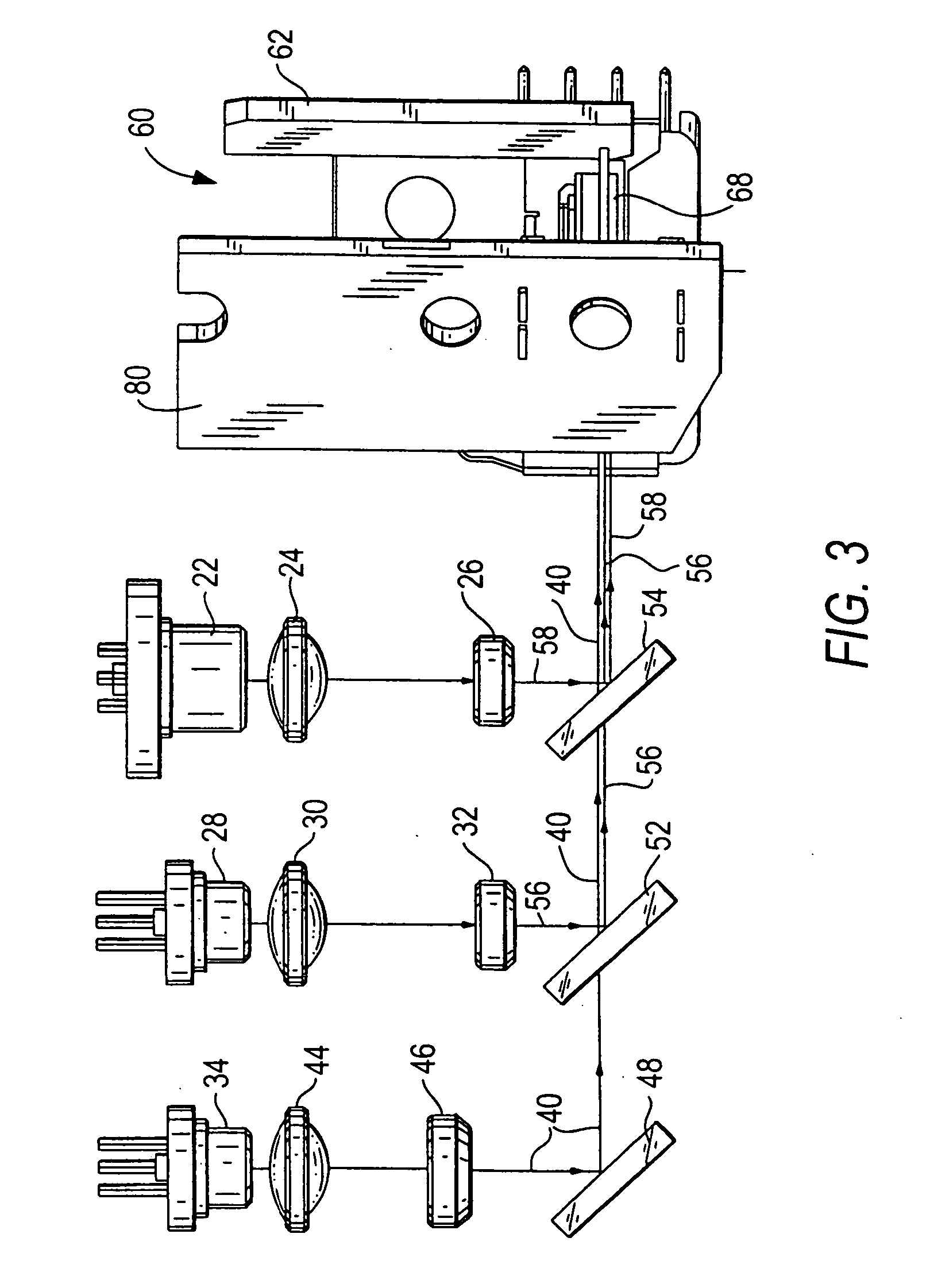
[0029] Referring to FIGS. 2 and 3, the arrangement 20 includes a solid-state, preferably a semiconductor laser 22 which, when energized, emits a bright red laser beam 58 at about 630-675 nanometers. Lens 24 is a biaspheric convex lens having a positive focal length and is operative for collecting virtually all the energy in the red beam and for producing a diffraction-limited beam. Lens 26 is a concave len...


PUM


Abstract

An image projection system projects an image on a projection screen having phosphor particles for converting incident violet light into green light which, together with red and blue light, creates the image in full color. The phosphor particles are bound in a binding material whose index of refraction matches the index of refraction of the phosphor particles to reduce back scattering of light.

Description

BACKGROUND OF THE INVENTION [0001] 1. Field of the Invention [0002] The present invention generally relates to projecting a two-dimensional image in color on a rear projection screen while maintaining low power consumption, high resolution, miniature compact size, quiet operation and minimal vibration. [0003] 2. Description of the Related Art [0004] It is generally known to project a two-dimensional image on a screen based on a pair of scan mirrors which oscillate in mutually orthogonal directions to scan a laser beam over a raster pattern. However, the known image projection systems project the image with limited resolution, typically less than a fourth of video-graphics-array (VGA) quality of 640×480 pixels. Red, blue and green lasers are employed to project the image in color. The physical size and power consumption of the known projection systems are relatively high, thereby rendering them impractical for use in miniature, hand-held, battery-operated applications, due in large p...

Claims


Application Information

Patent Timeline
Patent Type & Authority Applications(United States)
IPC IPC(8): G03B21/60
CPCG03B21/10G03B21/14G03B21/60H04N9/3129G03B21/204
Inventor STERN, MIKLOSYAVID, DMITRIY
Owner MICROVISION
Learn More