Pseudo-random number sequence output unit, transmitter, receiver, communication system and filter unit

a pseudo-random number sequence and output unit technology, applied in pulse manipulation, pulse technique, instruments, etc., can solve the problem of unable to obtain accurate results by dsp implementation or computer calculation, and difficulty in building a physical circuit or device for generating spreading codes, so as to eliminate redundant calculations

Inactive Publication Date: 2007-05-03
UMENO KEN +1
View PDF9 Cites 39 Cited by
  • Summary
  • Abstract
  • Description
  • Claims
  • Application Information

AI Technical Summary

Benefits of technology

[0114] In the present invention, the sequence initial values Yk (1≦k≦s) can be defined as the periodic points of period N of the dynamical system Xn+1=T(pk, Xn) obtained by chaos mapping T(pk, •). Use of this periodic property eliminates redundant calculation to enable high-speed pseudo-random number generation.

Problems solved by technology

This means that at the same bit error rate the number of simultaneously connected users K is 15% greater than the theoretical limit number of users of an asynchronous CDMA communication system using pseudo-white noise as the spreading codes.
When an attempt is made to generate such spreading sequences with a DSP (Digital Signal Processor) or the like and utilize them in a mobile phone system, for example, the following problems arise owing to the need for high-speed and low power consumption.
First, owing to the fact that the spreading codes are generated by piecewise-linear maps of very large slope, accurate results cannot be obtained by DSP implementation or computer calculation because of high digit dropout.
This makes it difficult to construct a physical circuit or device for generating the spreading codes.
Second, the piecewise-linear maps with the parameter that determines how the correlation function attenuates cannot be freely designed with respect to an arbitrary r (−1
Actual configuration of a CDMA communication system using the method taught by this paper is therefore difficult.
It is therefore difficult to cope with an increase in the number of users.
Communication security is therefore poor.
The teachings of this paper offer no remedy for any of these five problems.

Method used


Image

  • Pseudo-random number sequence output unit, transmitter, receiver, communication system and filter unit
  • Pseudo-random number sequence output unit, transmitter, receiver, communication system and filter unit
  • Pseudo-random number sequence output unit, transmitter, receiver, communication system and filter unit

Examples


first embodiment

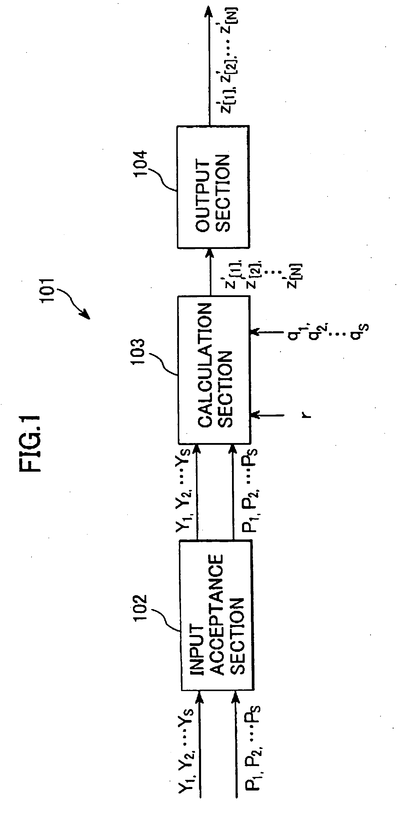
[0133]FIG. 1 is a schematic diagram (data flow chart) showing the general configuration of a pseudo-random number sequence output unit 101 that is a first embodiment of the present invention. Explanation will now be made with reference to this figure.

[0134] The pseudo-random sequence output unit 101 of this embodiment is equipped with an input acceptance section 102, a calculation section 103 and an output section 104. It outputs a pseudo-random number sequence of length N (1≦N) in response to s (1≦s) number of prescribed positive integers q1, q2, . . . , q5, a prescribed real impulse constant r (−1

[0135] The input acceptance section 102 accepts input of the following sequence initial values and integer parameters: [0136] s number of real number sequence initial values Y1, Y2, . . . , Ys; provided that −112s[0137] s number of integer parameters p1, p2, . . . , ps; provided that 2≦p1, 2≦p2, . . . 2≦ps and for which q1 mod p1≠0, q2 mod ...


PUM


Abstract

A pseudo-random number sequence output unit responsive to s (1≦s) number of prescribed positive integers q1, q2, . . . , qs, a prescribed real impulse constant r (−1<r<1), and a prescribed non-zero real constant C for outputting a pseudo-random number sequence of length N (1≦N), which output unit includes: an input acceptance section that accepts input of s (1≦s) number of real number sequence initial values Y1, Y2, . . . , Ys (−1<Y1<1, −1<Y2<1, . . . , −1 Ys<1), and s number of integer parameters p1, p2, . . . , ps (2≦p1, 2≦p2, . . . 2≦ps) for which q1 mod p1≠0, q2 mod p2≠0 . . . , qs mod ps≠0 respectively hold with respect to the prescribed positive integers q1, q2 . . . qs; a calculation section that uses the prescribed real impulse constant r, the prescribed non-zero real constant C, the sequence initial values Y1, Y2, . . . , Ys, the integer parameters p1, p2, . . . , ps, the prescribed positive integers q1, q2, . . . , qs and integers j (1≦j≦s), m (1≦m≦2N−2) and n (1≦n≦2N−1) to calculate from the recurrence formula Tp⁡(cos⁢ ⁢θ)=T⁡(p,cos⁢ ⁢θ)=cos⁡(p⁢ ⁢θ)yj⁡[1]=Yjyj⁡[m+1]=T⁡(pj,yj⁡[m])z⁡[n]=∏j=1s⁢T⁡(qj,yj⁡[n])a pseudo-random number sequence z′[1], z′[2], . . . , z′[N] of length N that satisfies z′⁡[1]=⁢C⁢∑j=1N⁢(-r)j⁢z⁡[j],z′⁡[2]=⁢C⁢∑j=1N⁢(-r)j⁢z⁡[j+1],⋮⁢z′⁡[N]=⁢C⁢∑j=1N⁢(-r)j⁢z⁡[j+N-1]; ⁢andan output section that outputs the pseudo-random number sequence z′[1], z′[2], . . . , z′[N]. A transmitter, receiver and communication system that utilize the output unit, a filter unit, a pseudo-random number sequence output method, transmission method, receiving method and filtering method are provided. A computer-readable data recording medium recorded with a program for operating the transmitter, receiver, communication system and implementing the output, transmission and receiving methods is also provided.

Description

CROSS-REFERENCE TO RELATED APPLICATION [0001] This is a Divisional Application of and claims the benefit of priority under 35 U.S.C §120 from U.S. Ser. No. 09 / 820,826, filed Mar. 30, 2001, the entire contents of which, are incorporated herein by reference. The present application also incorporates herein by reference the entire contents of Japanese application number, 2000-107047, filed Apr. 7, 2000.BACKGROUND OF THE INVENTION [0002] 1. Field of the Invention [0003] This invention relates to a pseudo-random number sequence output unit, transmitter, receiver, communication system and filter unit, a pseudo-random number sequence output method, transmission method and receiving method, and a data recording medium. [0004] This invention particularly relates to an output unit and output method suitable for outputting pseudo-random number sequences usable as the spreading codes of an asynchronous CDMA (Code Division Multiple Access) system for satellite, point-to-point, mobile phone and P...

Claims


Application Information

Patent Timeline
Patent Type & Authority Applications(United States)
IPC IPC(8): H03H7/30H04B1/00G06F7/58H03H17/02H03K3/84H04B1/707H04J13/00H04J13/10
CPCG06F7/586H04B1/707H04J13/0018H04J13/0022H04J13/10
Inventor UMENO, KEN
Owner UMENO KEN
Why Eureka
Try Eureka