Self-attaching fastener and panel assembly, method of installation and die member

a fastener and panel technology, applied in the direction of threaded fasteners, screwing, manufacturing tools, etc., can solve the problems of increasing the cost, the tubular barrel portion is subject to cracking, and the integrity of the fastener and panel assembly is not sufficient for commercial applications, so as to achieve less damage or wear, less expensive, and easy to form

Active Publication Date: 2007-05-03
PENN AUTOMOTIVE INC
View PDF18 Cites 4 Cited by
  • Summary
  • Abstract
  • Description
  • Claims
  • Application Information

AI Technical Summary

Benefits of technology

[0012] The die member of this invention for attaching a self-attaching fastener having a fastener portion and an integral tubular barrel portion having a free open end to a panel includes a central die post or land having a diameter generally equal to or less than the inner diameter of the open end of the tubular barrel portion configured to receive the free open end of the tubular barrel portion, a moat or trough having a planar die surface extending generally perpendicular to an axis of the central die post surrounding the central die post spaced below a free end of the central die post adapted to coin and deform the tubular barrel portion axially and radially as described above, and a planar panel support surface surrounding the annular die surface spaced above a plane of the planar die surface. As will be understood by those skilled in this art, the preferred embodiment of the die member or die button of this invention is significantly less expensive than the die buttons disclosed in the above-referenced U.S. Pat. No. 4,915,558. As will be understood, the planar die surface may be more easily formed than the annular concave hemispherical surface disclosed in the above-referenced patent and is less subject to damage or wear. Further, lubrication of the tubular barrel portion is not required in most applications because the tubular barrel portion is not rolled and inverted in an annular hemispherical die cavity as described above and disclosed in the above-referenced U.S. Pat. No. 4,915,558.

Problems solved by technology

However, this fastener and panel assembly did not provide sufficient integrity for commercial applications.
There are, however, problems associated with the method of installation disclosed in the above-referenced U.S. Pat. No. 4,915,558.
First, the tubular barrel portion is subject to cracking as the barrel portion is deformed against the annular hemispherical die surface, particularly if the roll over diameter exceeds a certain size.
To reduce the frictional resistance, the barrel portion is coated with a lubricant, increasing the cost.
Further, the complex die buttons are relatively expensive to manufacture because of the configuration of the annular concave hemispherical die surface which must be polished to minimize friction between the barrel and the self-attaching fastener and the dimensions are critical to proper installation.
Another problem with the installation disclosed in this patent is that the barrel cracks during installation.

Method used


Image

  • Self-attaching fastener and panel assembly, method of installation and die member
  • Self-attaching fastener and panel assembly, method of installation and die member
  • Self-attaching fastener and panel assembly, method of installation and die member

Examples


Embodiment Construction

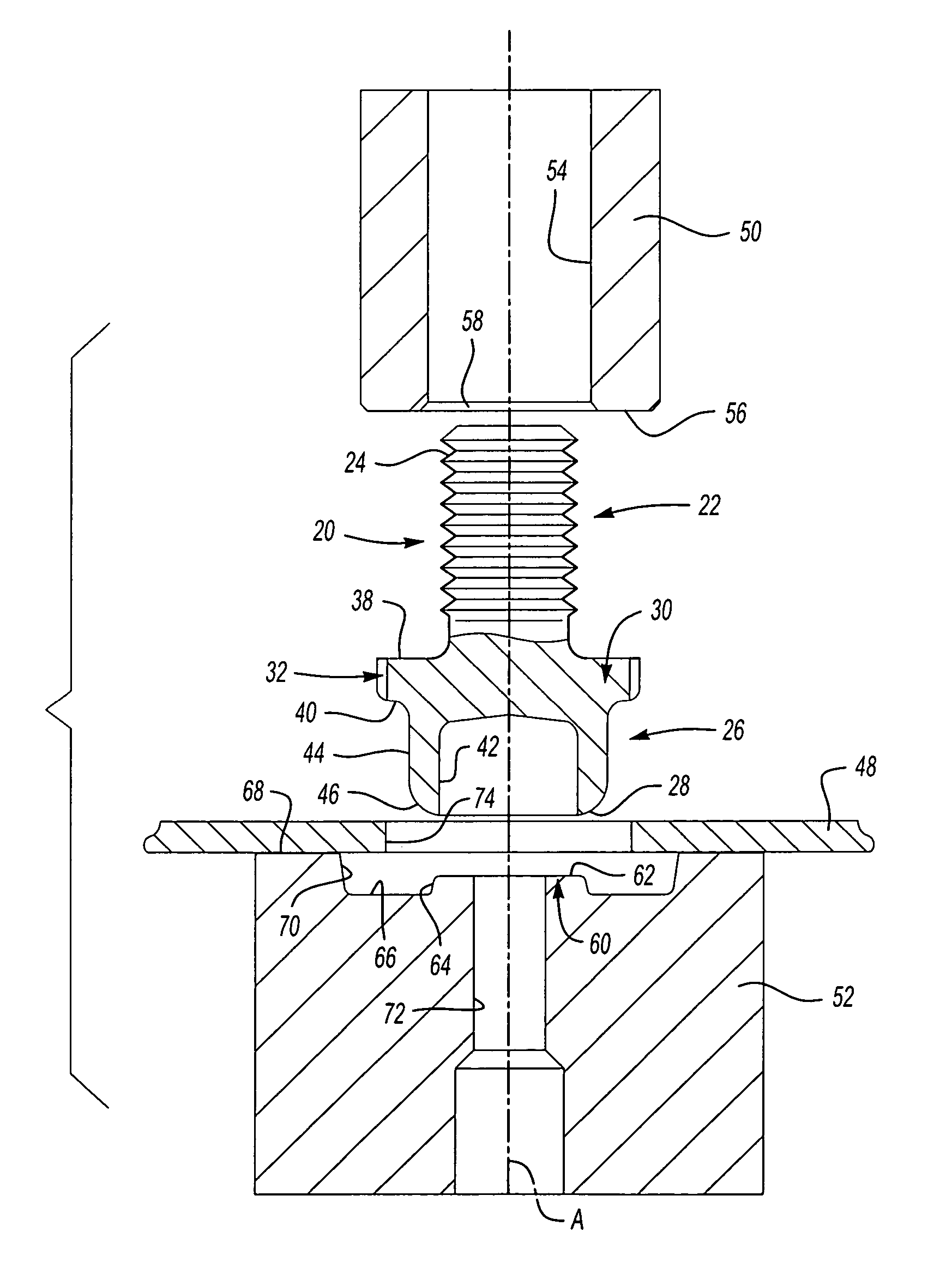
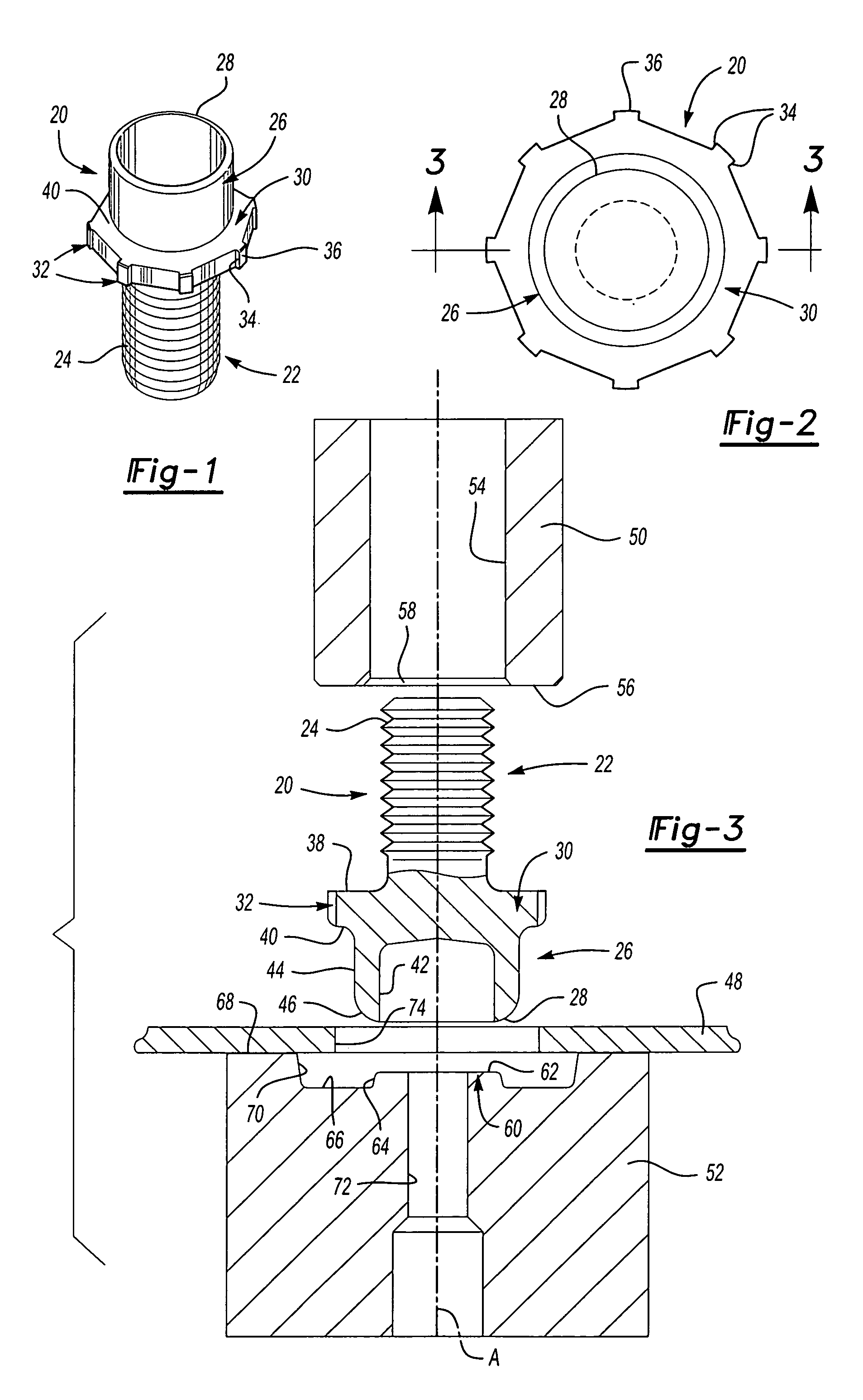
[0024] As set forth above, and discussed further hereinbelow, the embodiments of the self-attaching fastener and panel assembly, method of installing a self-attaching fastener in a panel and die member of this invention are disclosed for illustrative purposes only and do not limit this invention except as set forth in the appended claims. FIGS. 1 and 2 illustrate one preferred embodiment of a male self-attaching fastener which may be utilized in forming a self-attaching fastener and panel assembly of this invention utilizing the method of installation of this invention. As also set forth above, one advantage of the method of installation and die member of this invention is that a “conventional” self-attaching fastener may be utilized to form the self-attaching fastener and panel assembly of this invention. The embodiment of the self-attaching fastener shown in FIGS. 1 and 2 may be substantially identical to the embodiment of the self-attaching fastener shown in co-pending U.S. paten...


PUM

PropertyMeasurementUnit
diameteraaaaaaaaaa
thicknessaaaaaaaaaa
inner diameteraaaaaaaaaa

Abstract

A self-attaching fastener and panel assembly wherein the free end of the tubular barrel portion is coined and deformed axially and radially outwardly against a planar die face into an annular shape having a planar annular bearing surface supporting the panel and a flat end face. The die includes a central post and an annular planar die surface extending substantially perpendicular to the longitudinal axis of the die member. The method of installation includes coining and deforming the barrel portion axially and radially eliminating cracking of the barrel, frictional resistance and hoop-stress.

Description

FIELD OF THE INVENTION [0001] This invention relates to a self-attaching fastener and panel assembly, wherein the fastener is permanently attached to a panel, a method of attaching a self-attaching fastener to a panel and a die member adapted to form the self-attaching fastener and panel assembly and method of this invention. BACKGROUND OF THE INVENTION [0002] The predecessor in interest of the assignee of this application, Multifastener Corporation, first invented self-attaching fasteners over 50 years ago. As used herein, the term self-attaching fastener includes male and female self-piercing and self-clinching fasteners which are permanently attached to a panel, including pierce and clinch nuts. studs, bolts and the like, and pierce and clinch nuts and other female fasteners of this type. Self-attaching fasteners include a fastener portion, such as a threaded or unthreaded shank portion in the case of male fasteners, or a threaded or unthreaded bore in the case of female fastener...

Claims


Application Information

Patent Timeline
Patent Type & Authority Applications(United States)
IPC IPC(8): F16B39/00
CPCB23P19/062Y10T29/49956Y10T29/49915Y10T403/4949Y10T29/5377Y10T29/5343Y10T29/49833Y10T29/49908Y10T29/49938Y10T29/49954Y10T29/49835Y10T29/49837Y10T29/53709Y10T29/49897Y10T403/4966F16B37/065
Inventor KOVAC, ZDRAVKO
Owner PENN AUTOMOTIVE INC
Why Eureka
Try Eureka