System and method for determining the bearing of a source location from a receiver location

a technology of source location and receiver location, applied in the field of system and method for determining the bearing of a source location from a receiver location, can solve the problem of increasing the danger of the soldier and achieve the effect of reducing the ambiguity

Inactive Publication Date: 2007-05-03
AVAGO TECH WIRELESS IP SINGAPORE PTE
View PDF4 Cites 41 Cited by
  • Summary
  • Abstract
  • Description
  • Claims
  • Application Information

AI Technical Summary

Benefits of technology

[0007] Other embodiments of the system comprise additional beatable signal sources spatially offset from the first beatable signal sou...

Problems solved by technology

It is preferable that the soldier's transceiver does not transmit his or her location to the UAV, si...

Method used


Image

  • System and method for determining the bearing of a source location from a receiver location
  • System and method for determining the bearing of a source location from a receiver location
  • System and method for determining the bearing of a source location from a receiver location

Examples


first embodiment

[0055] The receiver is provided with information indicating the phase relationship between the beatable signals as transmitted and the phase reference signal, the positional relationship between or among the signal sources at the source location, and other system conditions. Each beatable signal propagates along a respective signal path extending from the respective beatable signal source to the receiver. The beatable signals are received at the receiver. The receiver sums the beatable signal to form a sum signal that includes a beat signal component, and demodulates the sum signal to extract the beat signal component as a beat signal. The phase of the beat signal depends on the difference in the respective path lengths between the beatable signal sources and the receiver. The phase of the beat signal additionally depends on other system conditions, as will be described below. The receiver measures the phase difference between the beat signal and either the phase reference signal or...

second embodiment

[0100] In a system based on system 10 for determining the bearing of source location 32 from receiver location 34 in accordance with the invention, the phase reference signal is single-frequency signal having a frequency ωTS equal to one half of the frequency difference Δωbetween the first frequency ω1 of the first beatable signal and the second frequency ω2 of the second beatable signal, i.e., ωTS=Δω / 2=(ω1−ω2) / 2. Phase reference signal source 80 transmits such phase reference signal directly. Since the phase reference signal is transmitted directly, receiver 100 does not subject the received phase reference signal to demodulation.

third embodiment

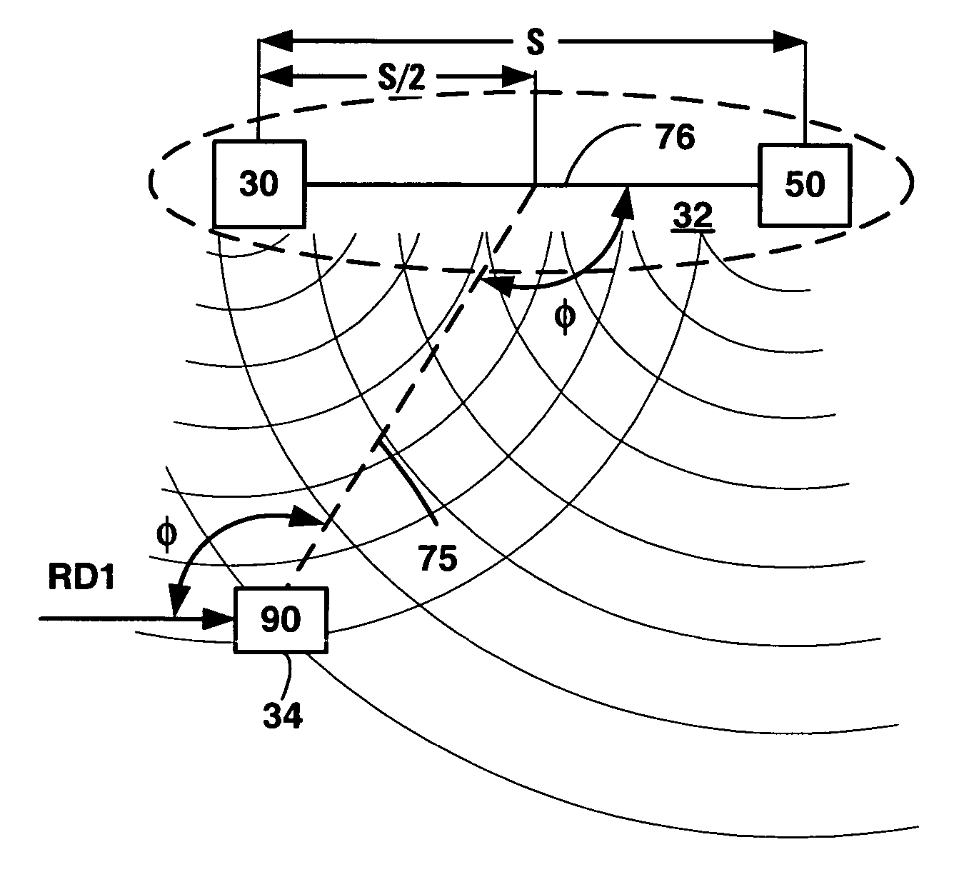
[0101]FIG. 6A is a schematic drawing showing a system 11 for determining the bearing of source location 32 from receiver location 34 in accordance with the invention. In system 11, located at source location 32 are first beatable signal source 30 and second beatable signal source 50 as described above with reference FIG. 5A. Additionally located at source location 32 is phase reference signal source 80. However, the positional relationship among first beatable signal source 30, second beatable signal source 50, phase reference signal source 80 in system 11 differs from that in system 10 described above with reference to FIG. 5A in that phase reference signal source 80 and first beatable signal source 30 are collocated at the first position. The second beatable signal source is spatially offset from the first beatable signal source and the phase reference signal source by distance S in first reference direction RD1. First beatable signal source 30, second beatable signal source 50, a...


PUM


Abstract

The system comprises a first beatable signal source, a second beatable signal source, a phase reference signal source and a receiver. The first beatable signal source and the second beatable signal source are located at the source location; the receiver is located at the receiver location. The phase reference signal source is operable to generate a phase reference signal. The first beatable signal source is operable to transmit a first beatable signal. The second beatable signal source is spatially offset from the first beatable signal source in a reference direction, and is operable to transmit a second beatable signal differing in frequency from the first beatable signal by a frequency difference. The first beatable signal and the second beatable signal collectively have a phase relationship with the phase reference signal. The receiver is structured to receive the first beatable signal and the second beatable signal and is operable to determine a direction angle, relative to the reference direction, of the source location from the receiver location. The receiver performs operations that comprise measuring a phase difference between a beat signal and either the phase reference signal or an additional beat signal, and determining the direction angle from the measured phase difference. The beat signal obtained by a process involving summing the first beatable signal and the second beatable signal. The additional beat signal is obtained by a process involving summing the first beatable signal and the phase reference signal. The bearing can be determined from the direction angle.

Description

BACKGROUND [0001] Communication systems in which the receiver tracks the transmitter typically allow the transmitter to consume less power than the non-tracking communication systems. Consider a satellite system that includes an earth-based receiver and an earth-orbiting transmitting satellite, for example. Currently, such satellite systems include a tracking processor that directs the earth station antenna towards the satellite and / or directs the satellite antenna towards the earth station antenna. Satellites can have simplified hardware if the earth station's antenna is continually steered to face the satellite. Additionally the transmitter in the satellite will consume less power. Lower-power transmitters reduce operational costs. For example, lower power consumption in the satellite transmitter can translate into a decrease in the cost of putting the satellite into orbit if the amount of hardware on the satellite is reduced. [0002] Some bidirectional transceiver systems have mul...

Claims


Application Information

Patent Timeline
IPC IPC(8): H04Q7/20G01S19/38G01S5/14
CPCG01S1/30G01S19/38
Inventor KOFOL, JOHN STEPHENTRUTNA, WILLIAM R. JR.FLOWER, GRAHAM
Owner AVAGO TECH WIRELESS IP SINGAPORE PTE
Why Eureka
Try Eureka