Servo-motor controlled hydraulic press, hydraulic actuator, and methods of positioning various devices

a hydraulic press and actuator technology, applied in the direction of presses, fluid couplings, clutches, etc., can solve the problem that the scale economy cannot be realized in this segment of the hydraulics industry

Inactive Publication Date: 2007-05-10
THE BECKWOOD CORP
View PDF12 Cites 44 Cited by
  • Summary
  • Abstract
  • Description
  • Claims
  • Application Information

AI Technical Summary

Benefits of technology

[0008] Thus, in a first preferred embodiment, the present invention provides a hydraulic system that includes an actuator, a pump, a servo-motor, and (optionally) an actuator position sensor, an actuator hydraulic pressure sensor, a comparator, a servo-valve, and a hydraulic fluid filter. The pump communicates with the actuator and provides hydraulic fluid to the actuator to move or pressurize it (i.e., to control the actuator). Also, the pump includes a hydraulic fluid inlet, a hydraulic fluid outlet, and a bypass path between the outlet and the inlet. The bypass path allows a portion of the hydraulic fluid to flow back around the pump with little opposition (i.e., bypass the pump). In response to a signal to control the actuator, the servo-motor (which is operatively coupled to the pump) drives the pump to supply hydraulic fluid to the actuator. As a result of the bypass path, the servo-motor is able to run substantially continuously.
[0009] Preferably, the pump is a reversible (or bi-directional) gear pump with an internal leak path that serves as the bypass path. Because the bypass path allows the motor to run substantially continuously, the bypass path causes the system to avoid the occurrence of the on / off hysteresis that is associated with the motor. In embodiments that include the position sensor and the comparator, the comparator generates the control signal by comparing the sensed actuator position with a desired position signal which can be time carrying. For those embodiments including the pressure sensor, the comparator can also generate the control signal based on a comparison of the sensed pressure and a desired actuator pressure. Since, in part, the servo-motor driven pump is insensitive to particulate contamination the system need not include a hydraulic fluid filter although it could include such a filter.

Problems solved by technology

Because that portion of the hydraulics industry that uses servo-valves is very small and specialized, economies of scale can not currently be realized in this portion of the hydraulics industry.

Method used


Image

  • Servo-motor controlled hydraulic press, hydraulic actuator, and methods of positioning various devices
  • Servo-motor controlled hydraulic press, hydraulic actuator, and methods of positioning various devices
  • Servo-motor controlled hydraulic press, hydraulic actuator, and methods of positioning various devices

Examples


Embodiment Construction

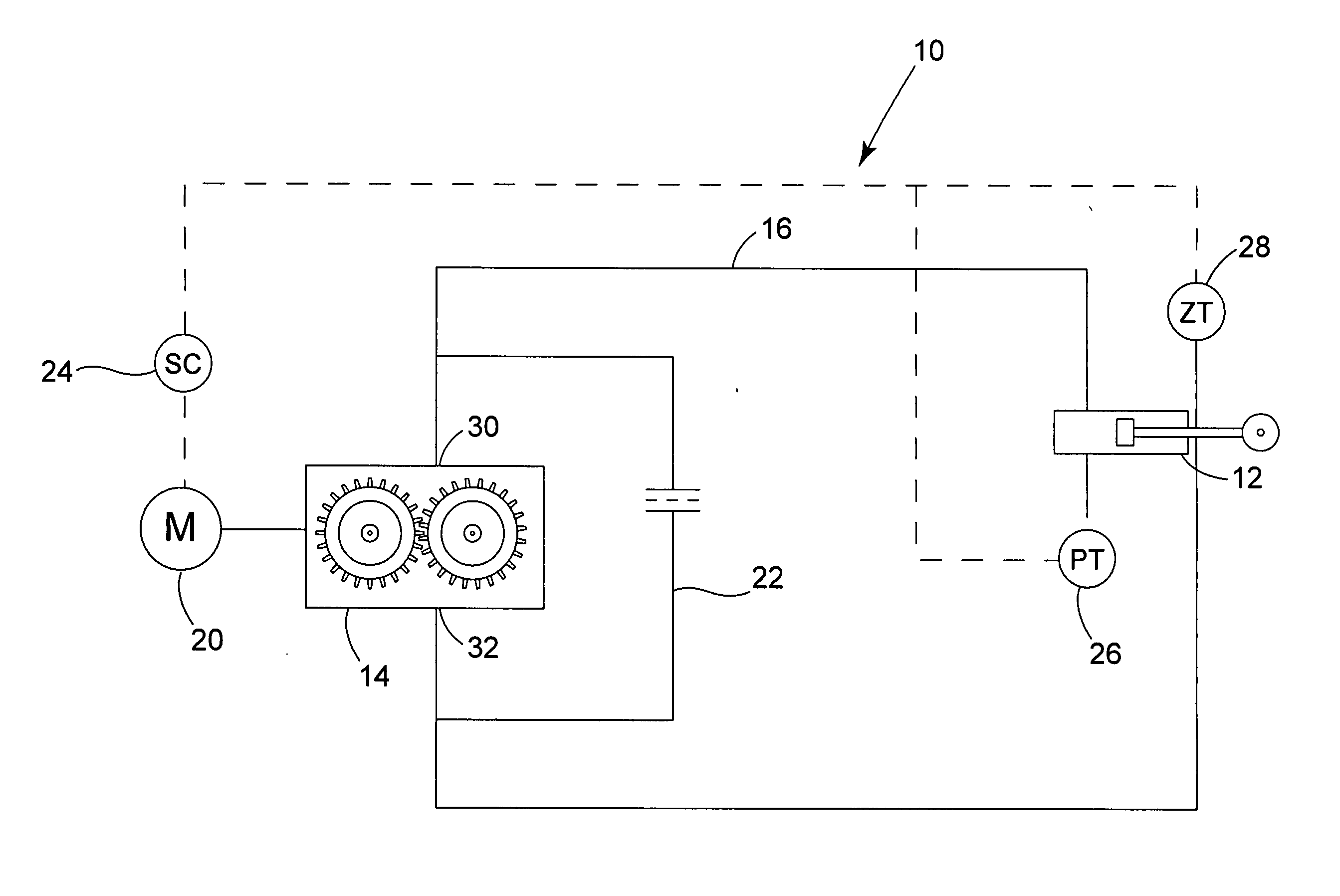
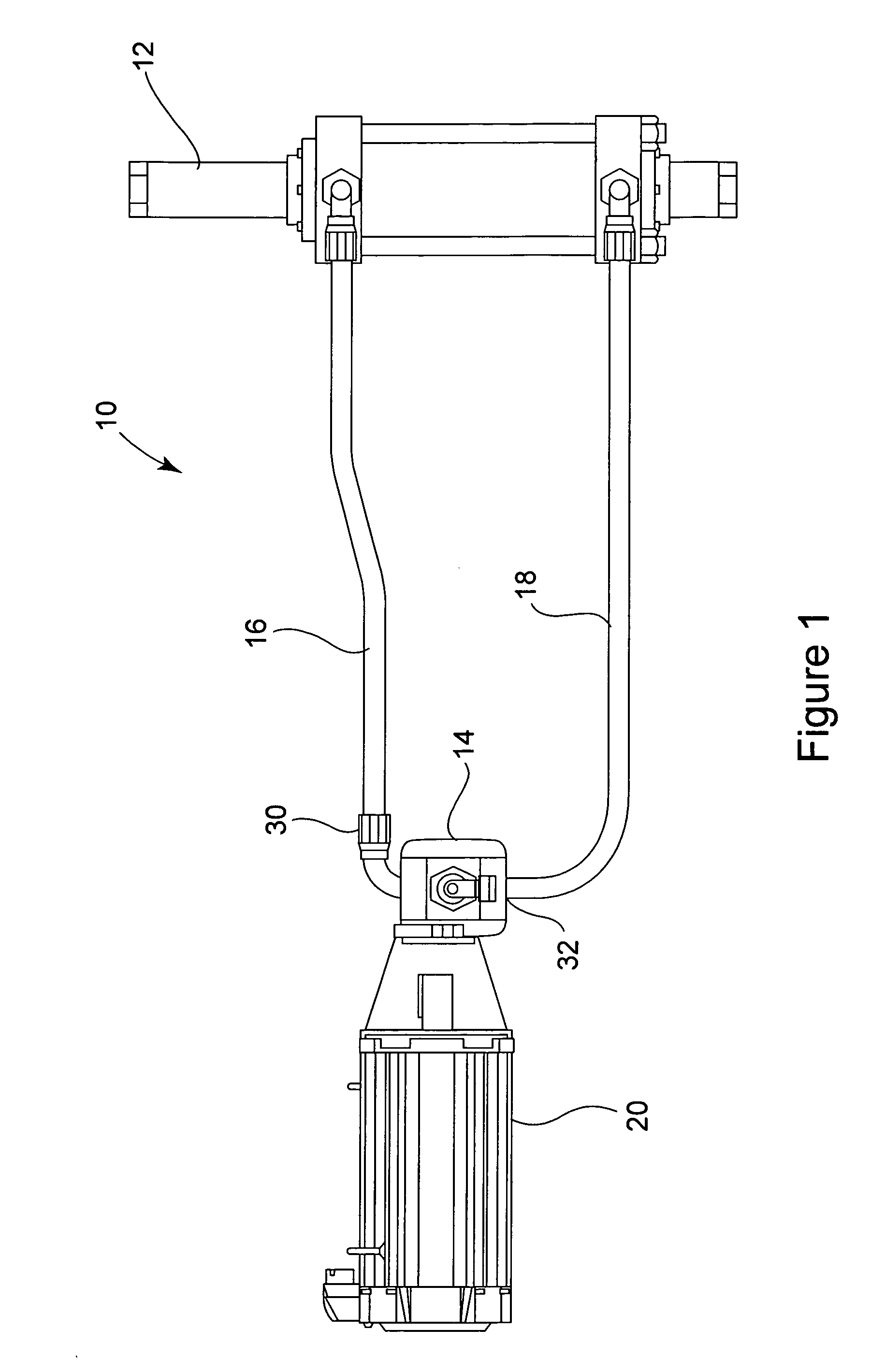
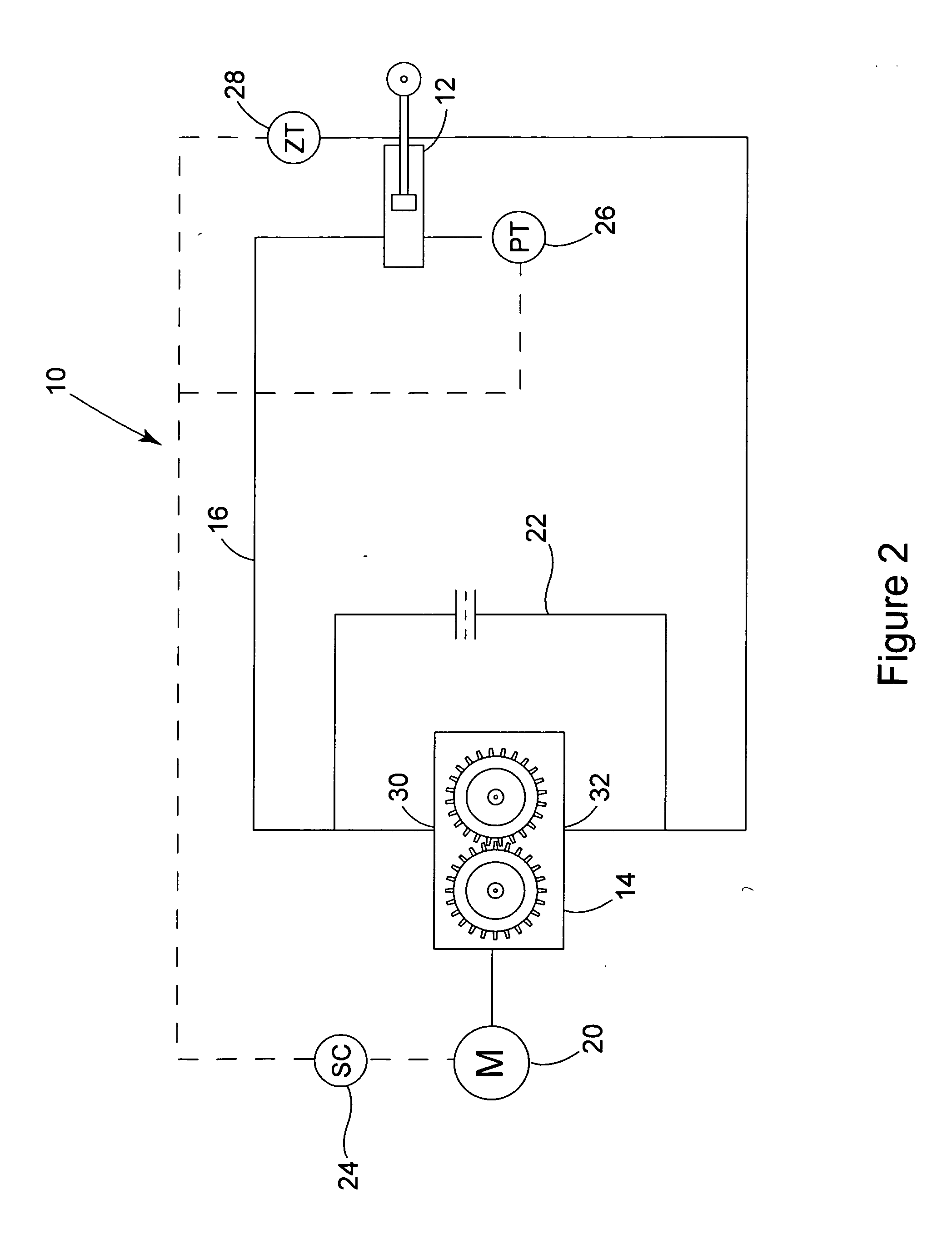
[0020] Referring to the accompanying drawings in which like reference numbers indicate like elements, FIG. 1 illustrates a hydraulic system that is constructed in accordance with the principles of the present invention. While the system 10 of the embodiment shown in FIG. 1 can be used in a hydraulic press, the system 10 could be used in any application where it is desired to position an actuator according to some predetermined path or in response to disturbances that change the desired position of, or force output by, the actuator. The system 10 includes an actuator 12, a pump 14, a pair of fluid lines 16 and 18 that interconnect the actuator 12 and the pump 14, and a servo-motor 20. The pump 14 shown is preferably a bi-directional gear pump while the servo-motor 20 is preferably any electric motor capable of driving the pump 14 and that is driven by a variable frequency drive or other servo-mechanism. In the preferred embodiment of FIG. 1 no servo-valve is included to position the ...


PUM


Abstract

A hydraulic system that includes an actuator, a pump, a servo-motor, and (optionally) an actuator position sensor, an actuator hydraulic pressure sensor, a comparator, a servo-valve, and a hydraulic fluid filter. The pump communicates with the actuator and provides hydraulic fluid to the actuator to control it. Also, the pump includes a hydraulic fluid inlet, outlet, and a bypass path from the outlet to the inlet. The bypass path allows a portion of the hydraulic fluid to bypass the pump. In response to a signal to control the actuator, the servo-motor (which is operatively coupled to the pump) drives the pump. As a result of the bypass path, the servo-motor is able to run continuously thereby avoiding the on/off hysteresis of the pump. Methods of positioning hydraulic actuators are also provided.

Description

FIELD OF THE INVENTION [0001] This invention relates generally to positioning and motion control systems and, more particularly, to hydraulic presses. BACKGROUND OF THE INVENTION [0002] Previously, when precision hydraulic motion control was required (as is often the case when a hydraulic press is used to manufacture a product), manufacturers relied on proportional or servo hydraulic valves for precision control of hydraulic actuators. These expensive hydraulic components require special electrical control components and rely upon advanced hydraulic filtration systems for proper operation. [0003] Yet, hydraulic presses have found many uses in low and moderate rate manufacturing processes. In addition, recent advances in pre-fill and regenerative hydraulic system design also allow high rate manufacturing using hydraulic presses. Hydraulic presses are preferred for many applications because their full tonnage can be developed at any point during the power stroke of the press. In contr...

Claims


Application Information

Patent Timeline
Patent Type & Authority Applications(United States)
IPC IPC(8): F16D31/02
CPCB30B15/166F15B21/087F15B2211/20515F15B2211/20538F15B2211/45F15B2211/50536F15B2211/6313F15B2211/6336F15B2211/7053
Inventor DEBUS, JEFFREY E.
Owner THE BECKWOOD CORP
Why Eureka
Try Eureka