Engine vibration suppression device and suppression method thereof

a technology of engine vibration and device, which is applied in the direction of engine starters, electric control, machines/engines, etc., can solve the problems of reducing torque variation, affecting the operation of the engine, so as to suppress the vibration of the vehicle body and reduce the effect of rolling vibration in the engine caused by torque variation

Inactive Publication Date: 2007-05-10
NISSAN MOTOR CO LTD
View PDF8 Cites 44 Cited by
  • Summary
  • Abstract
  • Description
  • Claims
  • Application Information

AI Technical Summary

Benefits of technology

[0006] Further, when the opening and closing timings of the intake valve are made variable and a decompression mechanism is employed to reduce the actual compression ratio by retarding the intake valve closing timing, thereby reducing the torque variation, the torque variation varies in accordance with the intake valve closing timing.
[0008] This invention has been designed in consideration of such technical problems in the prior art, and it is an object thereof to suppress rolling vibration in an engine caused by torque variation more effectively, and hence to suppress vehicle body vibration caused by the torque variation.

Problems solved by technology

However, torque variation at the time of engine startup varies according to the operating conditions of the engine, and cannot be calculated accurately from the crank angle alone.
During engine startup, however, if one of the cylinders was in the middle of the compression stroke when the vehicle stopped, compression at the time of startup begins from the stoppage point in this cylinder and not when the intake valve is closed, and hence the internal pressure of the cylinder is smaller than usual, leading to a reduction in torque variation.
Since torque variation varies in accordance with the operating conditions, and particularly during engine startup, it is impossible to calculate the torque variation accurately with the method described in JP11-336581A, in which the torque variation is calculated on the basis of the crank angle alone, and therefore an increase in vibration of the vehicle body accompanying resonance in the engine mounting system cannot be wholly prevented.

Method used


Image

  • Engine vibration suppression device and suppression method thereof
  • Engine vibration suppression device and suppression method thereof
  • Engine vibration suppression device and suppression method thereof

Examples


first embodiment

[0033] First Embodiment

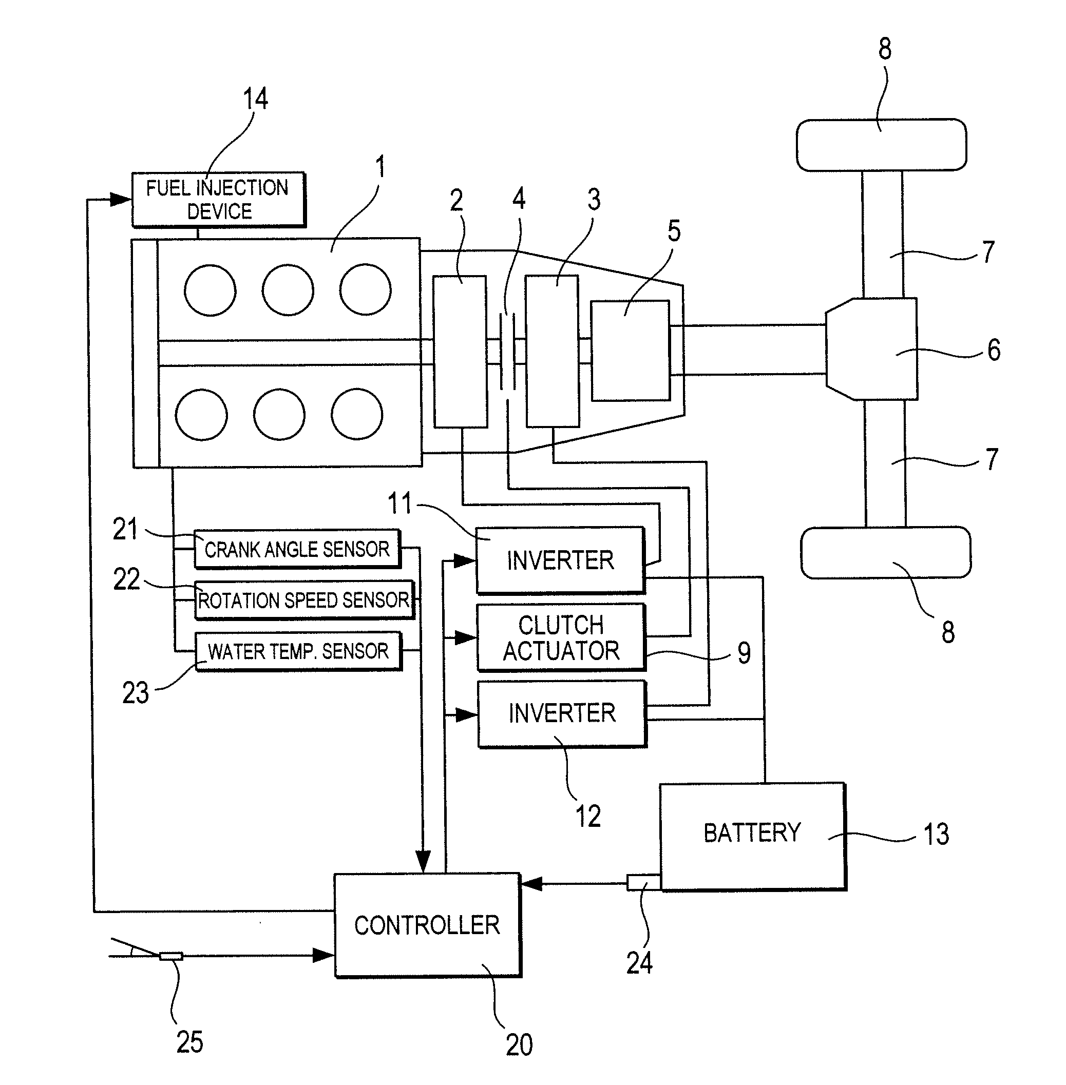
[0034]FIG. 1 shows the schematic constitution of a hybrid vehicle to which this invention is applied. The vehicle is a hybrid vehicle in which the wheels are driven by two types of power source, namely a diesel engine 1 and motor generators (rotating electrical machines) 2, 3.

[0035] The motor generator 2 mainly performs power generation and startup of the engine 1, while the motor generator 3 provides the engine 1 with auxiliary power and performs regeneration during deceleration.

[0036] The engine 1 is a six-cylinder, four-cycle engine, and an output shaft thereof is connected to a rotor of the motor generator 2. An output shaft of the rotor of the motor generator 2 is connected to an input shaft of a clutch 4. An output shaft of the clutch 4 is connected to a rotor of the motor generator 3, an output shaft of the motor generator 3 is connected to an input shaft of a transmission 5, and an output shaft of the transmission 5 is connected to drive shafts 7 via...

second embodiment

[0090] Second Embodiment

[0091]FIG. 10 shows the schematic constitution of a hybrid vehicle according to a second embodiment. Identical constitutions to those of the first embodiment have been allocated identical reference symbols, and where appropriate, description thereof has been omitted.

[0092] In the second embodiment, the motor generator 2 has a lower output than that of the first embodiment to achieve reductions in size and weight. Moreover, a decompression mechanism is provided to improve fuel economy and reduce torque variation by retarding the phase angle of the intake valve during engine startup so that the actual compression ratio is reduced, and therefore the torque variation in the engine 1 is reduced.

[0093] Furthermore, to purify a catalyst device for the purpose of exhaust gas purification, a throttle valve (not shown) is disposed in the intake system for performing control to raise the exhaust gas temperature by controlling an air-fuel ratio to a rich side when the ...

third embodiment

[0133] Third Embodiment

[0134] The constitution of a hybrid vehicle according to a third embodiment is identical to that of the first embodiment shown in FIG. 1 except that the motor generator 2 of the first embodiment has been replaced by a smaller motor generator 2. Accordingly, the amount of torque that can be generated by the motor generator 2 is restricted, and if the torque command value T is calculated by adding the torque correction amount, i.e. the opposite phase of the torque variation, without modification to the basic torque for driving the motor generator 2 to rotate, similarly to the first embodiment, the torque command value T may exceed the maximum torque value Tmax m that can be generated by the motor generator 2. As described in the second embodiment, if the torque command value T exceeds the maximum torque value Tmax m that can be generated by the motor generator 2, the desired rotation increase speed cannot be obtained and the time required for startup lengthens. ...


PUM


Abstract

A controller (20) estimates an internal cylinder pressure of an engine (1) on the basis of the operating conditions of the engine (1), torque variation in the engine (1) is calculated on the basis of the estimated internal cylinder pressure, and an opposite phase torque of the torque variation in the engine (1) is calculated as a torque correction amount. The controller (20) then calculates a torque command value for a motor generator (2) by adding the torque correction amount to a basic torque value for driving the motor generator (2) to rotate, and performs torque control such that the torque of the motor generator (2) equals the torque command value.

Description

FIELD OF THE INVENTION [0001] This invention relates to a device which suppresses engine vibration, and particularly to a device which suppresses rolling vibration. BACKGROUND OF THE INVENTION [0002] In a hybrid automobile in which the vehicle is driven by a combination of an engine and a motor, an idle stop, in which the engine is halted temporarily while the vehicle is stationary, is performed to reduce fuel consumption. When the vehicle is started up again after executing an idle stop, the engine is cranked by the motor and thereby restarted. However, when the engine is restarted, torque variation is generated as intake air is compressed and expanded, leading to resonance in the engine mounting system and resulting in heavy vibration. [0003] If torque variation of an opposite phase to the torque variation is generated from the motor at this time, the torque variation can be canceled out, enabling a reduction in vibration, and hence in JP11-336581A, the torque variation in the eng...

Claims


Application Information

Patent Timeline
Patent Type & Authority Applications(United States)
IPC IPC(8): F02B75/06B60K1/02B60K6/442B60L15/20B60W10/06B60W10/08B60W20/00F02D29/02F02D29/06F02D45/00
CPCB60K6/442Y10T477/23B60W10/06B60W10/08B60W20/00B60W30/20B60W2710/083F02D35/024F02D41/065F02D41/083F02D41/1498F02D2200/1004F02N11/08F02N11/0814F02N19/00F02N99/006F02N2200/021F02N2200/022F02N2200/023F02N2300/104Y02T10/6234Y02T10/6286Y02T10/642Y02T10/7258B60L2240/423Y02T10/62Y02T10/64Y02T10/72B60W20/15B60W2510/06
Inventor ASAHARA, YASUYUKIFUJIKANE, KAZUHIRO
Owner NISSAN MOTOR CO LTD
Why Eureka
Try Eureka