Dynamic heat sink for light emitting diodes

a heat sink and diode technology, applied in the direction of thermoelectric devices, lighting and heating apparatuses, semiconductor devices for light sources, etc., can solve the problem of limit on the distance between the two positions, and achieve the effect of less power dissipation

Inactive Publication Date: 2007-05-10
UNIVERSAL MEDIA SYST
View PDF3 Cites 104 Cited by
  • Summary
  • Abstract
  • Description
  • Claims
  • Application Information

AI Technical Summary

Benefits of technology

[0018] The Present Invention is a dynamic heat sink that uses a thermoelectric cooler, such as a Peltier Junction, to move the heat at a LED junction to the other side of the cooling chip. This would allow the LED to run with more current in a much smaller area than a passive metal heat sink without burning out the junctions. The Present Invention would therefore permit a compact light device comprising a plurality of LED's to be constructed. Such a light device would be competitive with standard fluorescent bulbs by outputting light of equivalent brightness with less power dissipation.

Problems solved by technology

Furthermore, where a plurality of LED's are required for higher brightness, there are limits to how close they can be positioned next to one another due to the problem of heat dissipation.

Method used


Image

  • Dynamic heat sink for light emitting diodes
  • Dynamic heat sink for light emitting diodes
  • Dynamic heat sink for light emitting diodes

Examples


Embodiment Construction

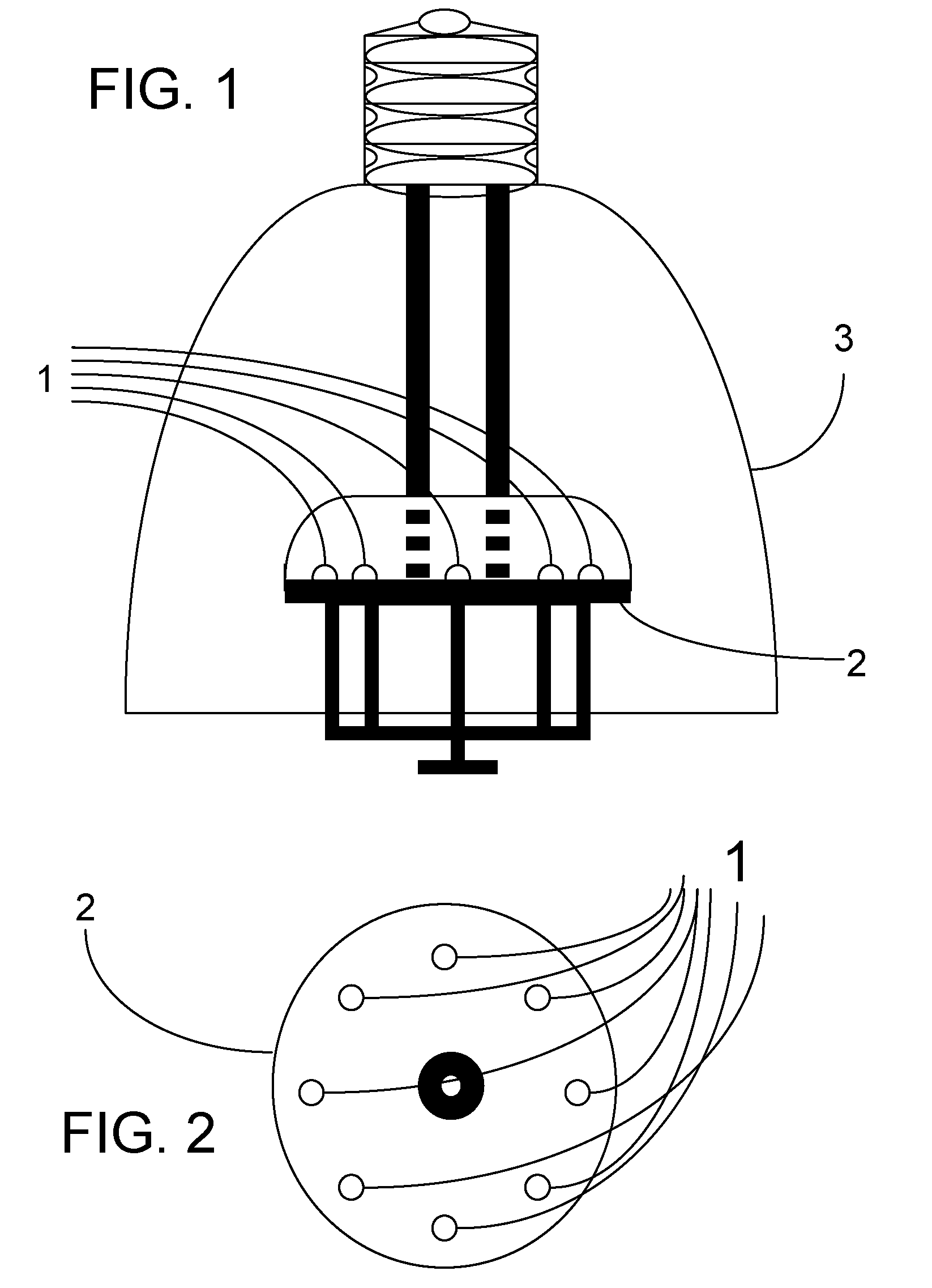
[0022]FIG. 1 is an elevational view schematic of a light device containing a plurality of LED's arranged in a cluster on a dynamic heat sink surface. In the figure, eight LED's, 1, are mounted with their heat sinks on plate 2. As previously discussed, copper and aluminum are excellent materials for fabrication of plate 2. LED's emit light which is reflected out of the device by reflector 3. Reflector 3 can have a simple paraboloid or ellipsoid shape with the focus in the center of the LED cluster plate. Alternatively, it can have a complex shape that would have multiple foci located at each LED position. A conventional or a Fresnel lens may also be placed at the output end of the lens to distribute the output light into a desired pattern. FIG. 2 is a plan view schematic showing the cluster of eight LED's of FIG. 1 mounted along with their dynamic heat sinks on circular plate 2.

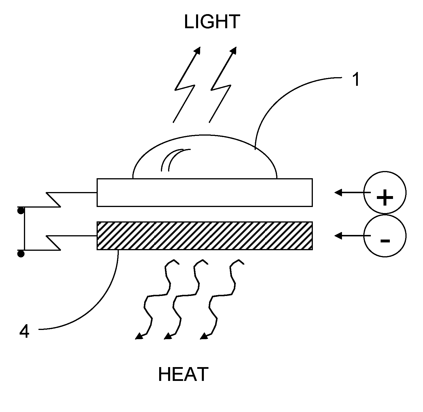
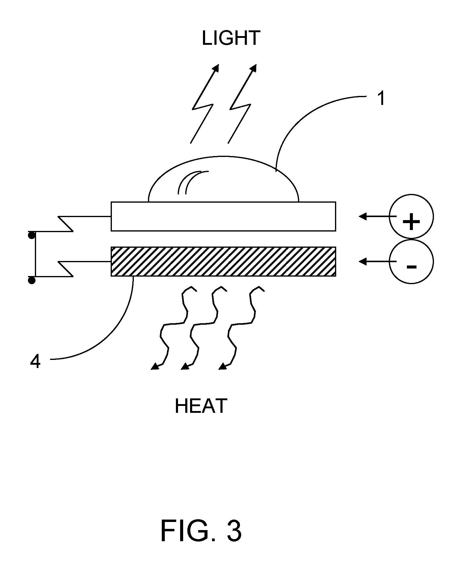
[0023]FIG. 3 shows a single LED 1 mounted on the cold side of a heat sink 4 that constitutes the Present I...


PUM


Abstract

Dynamic heat sink that uses a thermoelectric cooler, such as a Peltier Junction, to move the heat at a LED junction to the other side of the cooling chip. This would allow the LED to run with more current in a much smaller area than a passive metal heat sink without burning out the junctions. The Present Invention would therefore permit a compact light device comprising a plurality of LED's to be constructed. Such a light device would be competitive with standard fluorescent bulbs by outputting light of equivalent brightness with less power dissipation.

Description

CROSS REFERENCE TO RELATED APPLICATIONS [0001] This Present Application is the non-provisional counterpart of U.S. Provisional Patent Application Ser. No. 60 / 597,018 filed on Nov. 4, 2005, and claims the benefit of and priority to said provisional application, which is incorporated herein by reference in its entirety. This application is also related to U.S. Provisional Patent Application Ser. No. 60 / 596,809 filed on Oct. 21, 2005, and its non-provisional counterpart U.S. application Ser. No. 11 / 552,029 filed on Oct. 23, 2006, both of which are also incorporated herein by reference in their entirety.BACKGROUND OF THE INVENTION [0002] A light emitting diode (LED) must be mounted on a relatively large metal heat sink to dissipate the heat when the diode is run using high current. It is desirable to run LED's using high current, because the higher the current, the higher the brightness of the emitted light. Furthermore, where a plurality of LED's are required for higher brightness, the...

Claims


Application Information

Patent Timeline
Patent Type & Authority Applications(United States)
IPC IPC(8): H01L35/28
CPCF21Y2101/02H01L33/645F21V7/08F21V29/54F21V7/0008F21V7/06F21K9/13F21K9/23F21Y2115/10
Inventor PETROCY, RICHARD JOEL
Owner UNIVERSAL MEDIA SYST
Why Eureka
Try Eureka