Liquid ejection apparatus

Inactive Publication Date: 2007-05-10
SEIKO EPSON CORP
View PDF8 Cites 10 Cited by
  • Summary
  • Abstract
  • Description
  • Claims
  • Application Information

AI Technical Summary

Benefits of technology

[0012] Accordingly, it is an objective of the present invention to provide a liquid ejection apparatus that stabilizes the optical charac

Problems solved by technology

Therefore, the laser sputtering method is applicable only to certain types of substrates, making it difficult to form identification codes in a wider range of substrates.
In the waterjet method, water or dust or abrasive may splash onto and contaminate a substrate, when forming a code pattern on the substrate.
However, when drying droplets on a substrate,

Method used


Image

  • Liquid ejection apparatus
  • Liquid ejection apparatus
  • Liquid ejection apparatus

Examples


Example

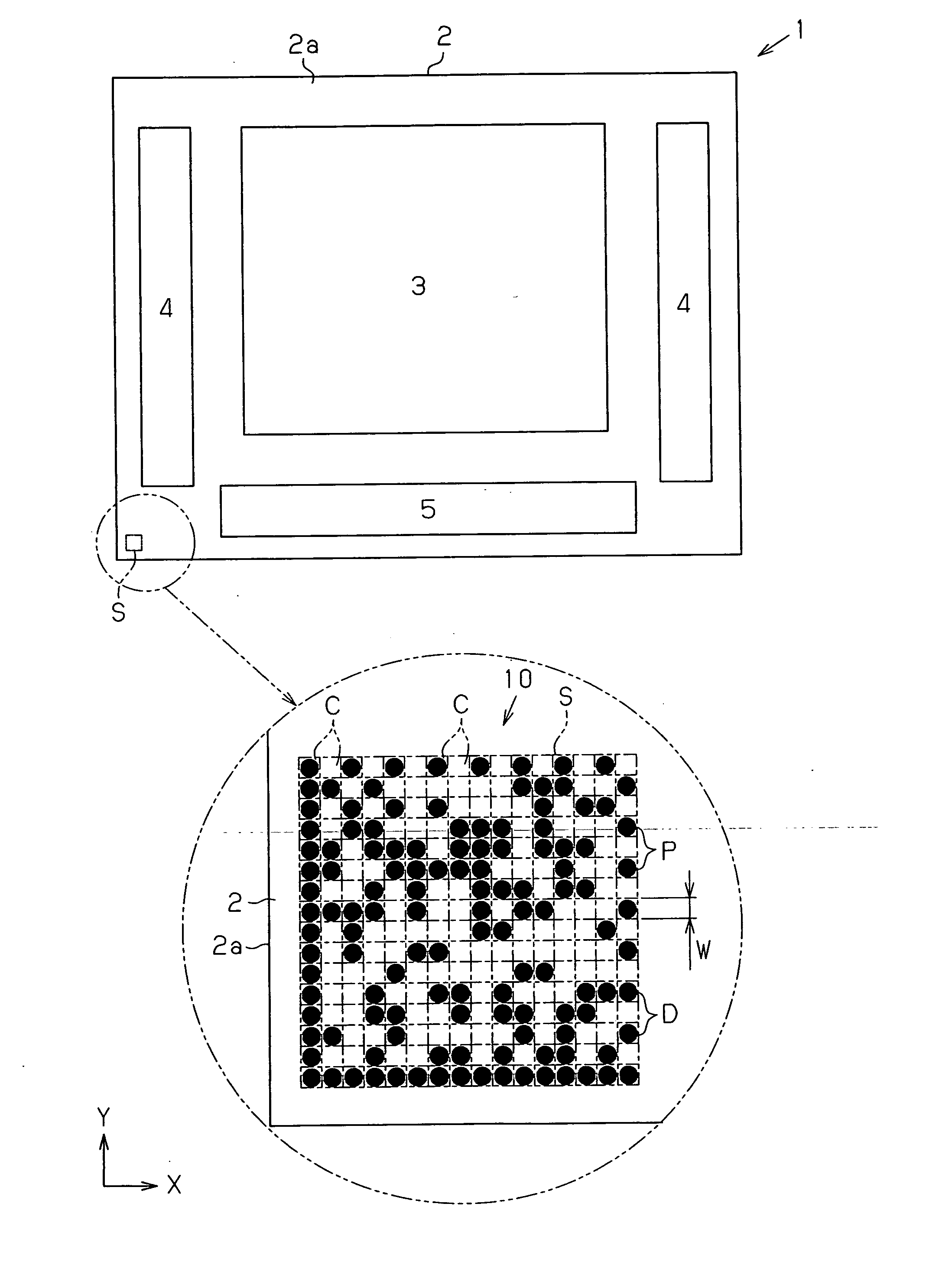
[0028] In the first embodiment, the center of each of the data cells C in which a dot D is formed will be referred to as an “ejection target position P” and the length of each side of each data cell C will be refereed to as a “cell width W”.

[0029] Each of the dots D is formed in a semispherical shape with an outer diameter equal to the cell width W. To form the dots D, droplets Fb of liquid containing metal particles (for example, nickel particles or manganese particles) as pattern forming material are ejected onto the corresponding cells C (the black cells C1). The droplets Fb in the cells C are then irradiated with laser beams, which dry and bake the droplets Fb (see FIG. 4), forming the dots D. Alternatively, the dots D may be formed simply by drying the droplets Fb through radiation of a laser beam.

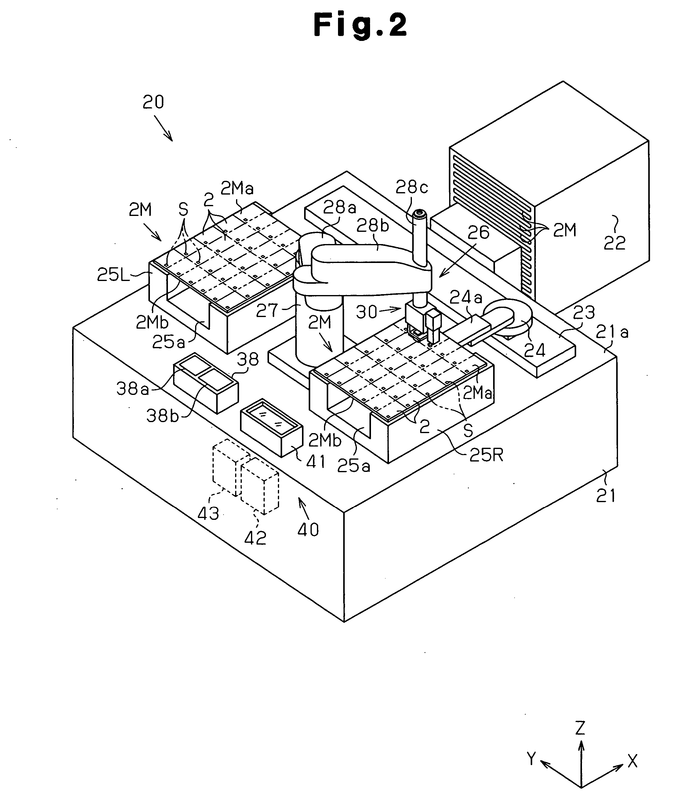
[0030] A liquid ejection apparatus 20 for forming the identification code 10 will hereafter be described. In the following case, a plurality of identification codes 10 will be forme...

Example

[0093] A second embodiment of the present invention will now be described with reference to FIG. 8. Same or like reference numerals are given to parts of the second embodiment that are the same as or like corresponding parts of the first embodiment and detailed description thereof will be omitted. In the following description of the second embodiment, the configuration of a maintenance mechanism 38 of the ejection head 32 will be explained in detail.

[0094] As shown in FIG. 8, a plate-like mirror securing section 45 is supported by a lower end of the laser head 37 in a manner movable in the direction defined by the height of the mirror securing section 45. The reflective mirrors M of the first embodiment are pivotally secured to a lower end of the mirror securing section 45. In the second embodiment, the mirror securing section 45 moves downward from the state in which the laser beams B are radiated (the state indicated by the double-dotted chain lines of FIG. 8). The reflective sur...


PUM


Abstract

A cleaning bath is provided on a base of a liquid ejection apparatus. A cleaning liquid supply section and a cleaning liquid discharge section are connected to the cleaning bath. The cleaning liquid supply section supplies cleaning liquid to the cleaning bath. The cleaning liquid discharge section drains the cleaning liquid from the cleaning bath. After having formed dots, a head unit is moved to the position immediately above the cleaning bath. Reflective mirrors are then immersed in the cleaning bath in the vicinity of an inlet pipe through which the cleaning liquid is introduced into the cleaning bath. An ejection head is also immersed in the cleaning bath in the vicinity of an outlet pipe through which the cleaning liquid is drained from the cleaning bath.

Description

CROSS-REFERENCE TO RELATED APPLICATIONS [0001] This application is based upon and claims the benefit of priority from prior Japanese Patent Application No. 2005-323808 filed on Nov. 8, 2005, the entire contents of which are incorporated herein by reference. BACKGROUND [0002] 1. Technical Field [0003] The present invention relates to a liquid ejection apparatus. [0004] 2. Related Art [0005] Typically, a display such as a liquid crystal display or an electroluminescence display includes a substrate that displays an image. The substrate has an identification code (for example, a two-dimensional code) representing encoded information including the site of production and the product number. The identification code is formed by structures (dots formed by colored thin films or recesses) that reproduce the identification code. The structures are provided in multiple dot formation areas (data cells) in accordance with a prescribed pattern. [0006] As a method for forming the identification co...

Claims


Application Information

Patent Timeline
IPC IPC(8): B41J2/16
CPCG02B27/0006H01L21/02H01L21/288H01L23/544
Inventor MIURA, HIROTSUNAIWATA, YUJI
Owner SEIKO EPSON CORP
Why Eureka
Try Eureka