Holographic multiplex recording method

Inactive Publication Date: 2007-05-10
TDK CORPARATION
View PDF2 Cites 0 Cited by
  • Summary
  • Abstract
  • Description
  • Claims
  • Application Information

AI Technical Summary

Benefits of technology

[0013] It is an object of this invention to eliminate distortion of a reproduction image by suppressing the nonuniformi

Problems solved by technology

Thus, nonuniformity is caused in the intensity of formed gratings (interference fringes), resulting in distortion of a reproduction image and an increase in bit error rate.
Although the recording scheduling is not required, a contrast distribution is generated in gratings to be recorded since remaining dynamic range and photosensitivity are nonuniform in a recording area to be newly recorded, causing a problem tha

Method used


Image

  • Holographic multiplex recording method
  • Holographic multiplex recording method
  • Holographic multiplex recording method

Examples


Example

[First Embodiment]

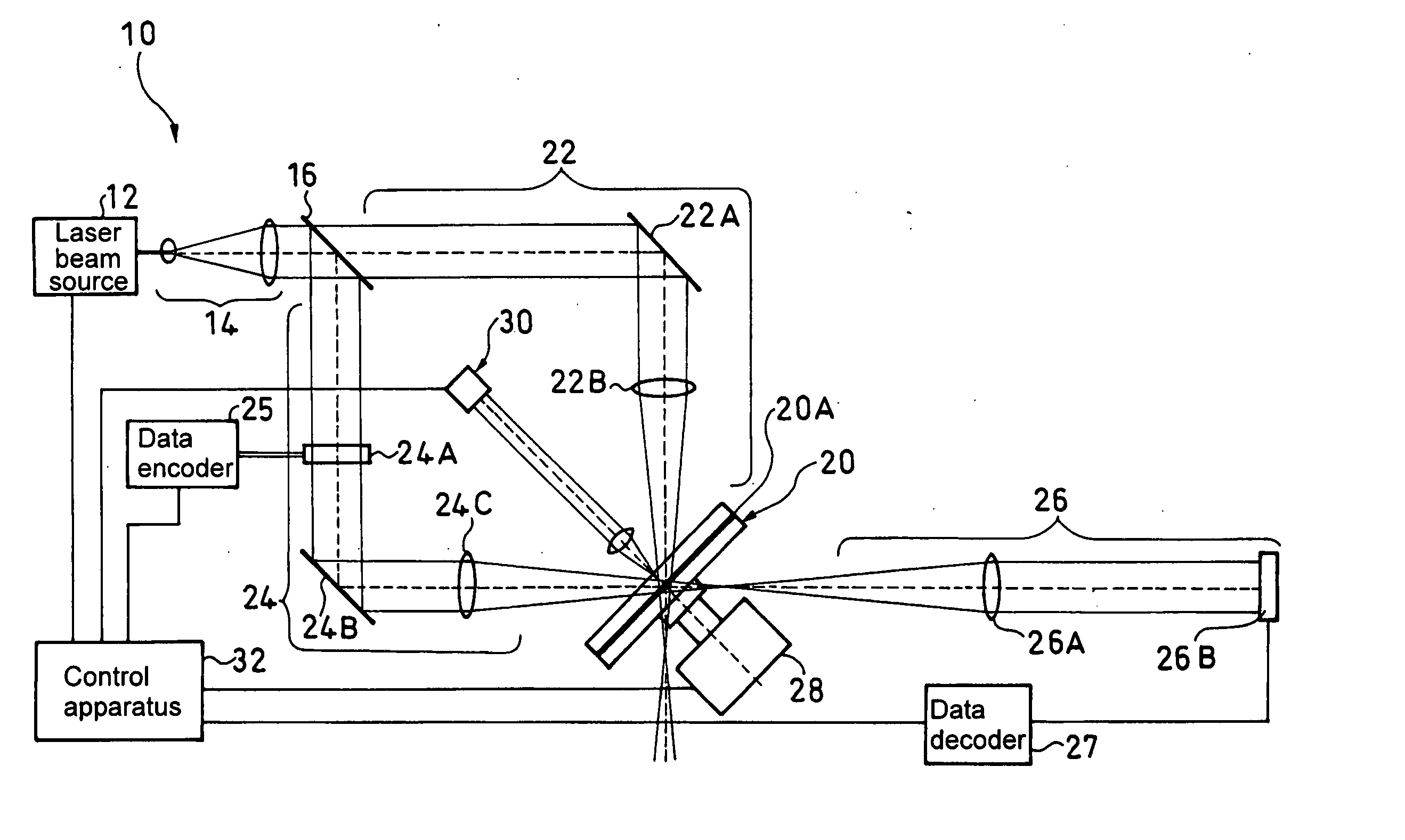
[0033]FIG. 1 shows an apparatus for embodying the holographic multiplex recording method of the present invention.

[0034] A holographic multiplex recording apparatus 10 is configured to include: a laser beam source 12; a beam expander 14 for expanding the beam diameter of the laser beam emitted from this laser beam source 12; a beam splitter 16 for splitting the laser beam having the beam diameter expanded by this beam expander 14 into a reference beam and an object beam; a reference optical system 22 for guiding the reference beam, which is the transmission beam of the abovementioned beam splitter 16, to a holographic recording medium 20; an object optical system 24 for guiding the object beam, which is the reflection beam of the abovementioned beam splitter 16, to the abovementioned holographic recording medium 20; an imaging optical system 26 which is arranged on a line extending the optical axis of the object beam having been projected onto the abovementioned ...

Example

[Second Embodiment]

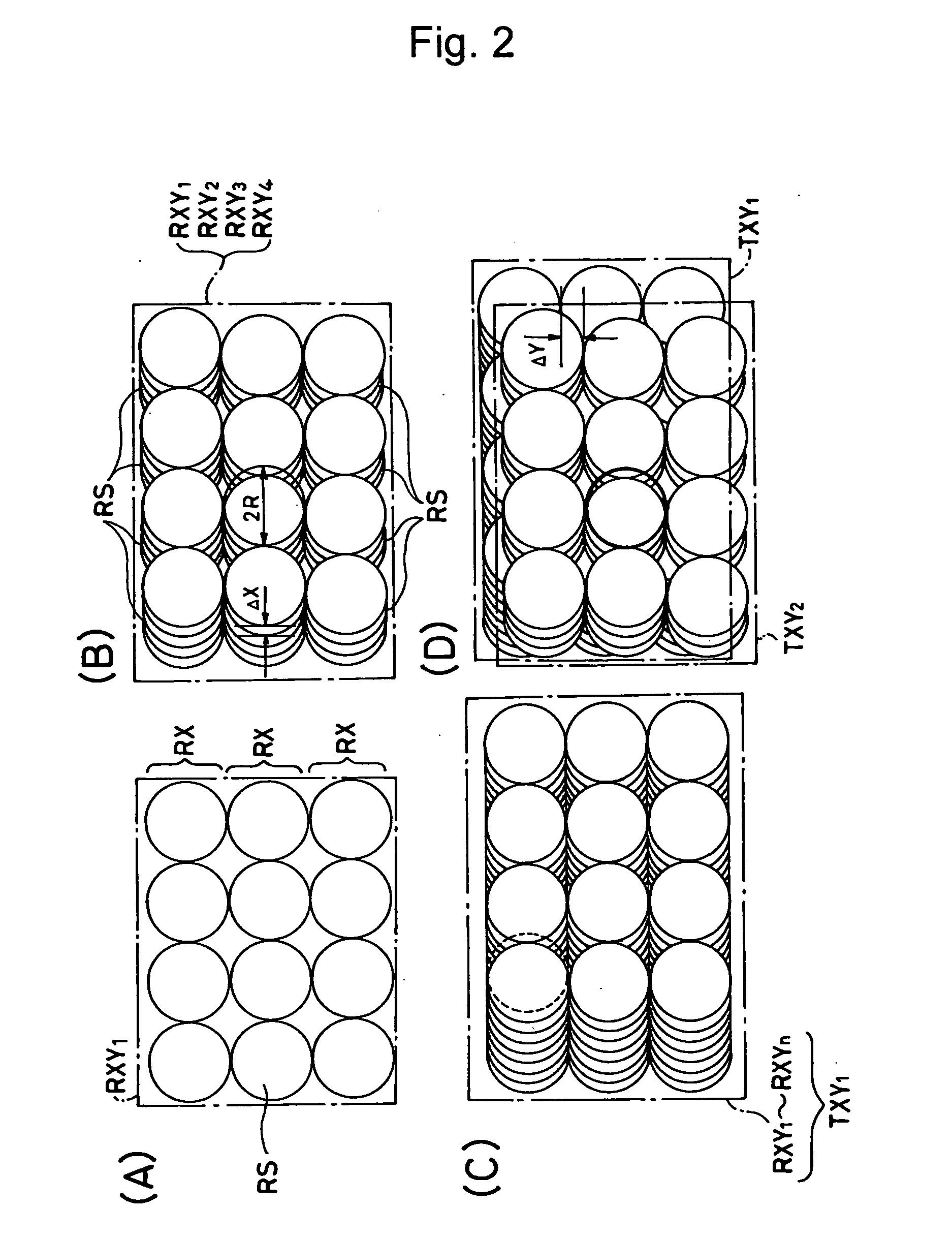
[0061] Next, a second embodiment will be described with reference to FIG. 3.

[0062] The second embodiment is configured to include: a Y-axis direction first multiplex recording step of forming a Y-axis direction first multiplex recording spot matrix TYX1 shown in FIG. 3(B) by arranging first-stage recording spot rows RX1 comprising recording spots RS arranged with a constant pitch in the X-axis direction and adjacent to each other without overlapping as shown in FIG. 3(A), in the Y-axis direction with a slight phase shift (ΔY) relative to one another; a Y-axis direction second multiplex recording step of forming a Y-axis direction second multiplex recording spot matrix TYX2 by arranging recording spot rows RX2 comprising the recording spots RS arranged with a constant pitch in the X-axis direction and adjacent to each other without overlapping with reference to a position slightly phase-shifted (ΔX) in the X-axis direction with respect to the abovementioned first...

Example

[Third Embodiment]

[0066] Next, a method of a third embodiment of the present invention will be described with reference to FIG. 6.

[0067] This holographic multiplex recording method forms the recording spots by repeating a first-stage X-axis direction multiplex recording step to a last-stage X-axis direction multiplex recording step.

[0068] The abovementioned first-stage X-axis direction multiplex recording step comprises: an X-axis direction first multiplex recording step of forming an X-axis direction first multiplex recording spot row XR1 by arranging the recording spots RS in the X-axis direction with a slight phase shift relative to one another as shown in FIG. 6(A); an X-axis direction second multiplex recording step of forming an X-axis direction second multiplex recording spot row XR2 by arranging the recording spots RS with a slight phase shift (ΔX) relative to one another in positions adjacent and parallel to the abovementioned X-axis direction first multiplex recording s...


PUM


Abstract

A holographic multiplex recording method is provided in which remaining dynamic range in each recording area is made more uniform upon holographic multiplex recording. In this holographic recording method, a first-stage recording spot row RX1 is formed by arranging recording spots RS in an X-axis direction without overlapping, and then a second-stage recording spot row RX2 formed of the recording spots RS without overlapping in the X-axis direction is recorded in a position for shift multiplex recording in a Y-axis direction. This is repeated to form a Y-axis direction first multiplex recording spot matrix TYX1. In this case, recording is performed to all recordable regions without shift multiplex recording in the X-axis direction. Subsequently, a Y-axis direction second multiplex recording spot matrix TYX2 is formed in a position shift-multiplexed in the X-axis direction with respect to the first-stage recording spot row RX1 initially recorded. The shift multiplex recording in the X-axis direction is performed in a similar manner up to a Y-axis direction last multiplex recording spot matrix TYXn to thereby complete the recording.

Description

TECHNICAL FIELD [0001] The present invention relates to a holographic multiplex recording method. BACKGROUND ART [0002] A holographic multiplex recording method has been proposed in which, when recording spots of interference fringes are formed in a recording layer of a holographic recording medium by projecting an object beam and a reference beam, a beam spot which is an overlapping projection region of the object beam and the reference beam is slightly shifted along the surface of the abovementioned recording layer for each projection to thereby form the recording spots superimposed with a slight shift in the X-axis direction and the Y-axis direction (see a reference, 10 May 1996 / Vol. 35, No.14 / APPLIED OPTICS P2403-2417). [0003] At this time, as shown in FIG. 9, the recording spots 1A, 1B, 1C, 1D, 1E, and 1F are formed so as to be shifted from one another in the X-axis direction in FIG. 9 by a shift amount Δ. [0004] For example, remaining dynamic range (DR) in the recording layer ...

Claims


Application Information

Patent Timeline
IPC IPC(8): G11B7/00G03H1/04G03H1/26G03H1/28G11B7/0065G11B7/007
CPCG03H1/26G11B7/0065G11B7/007G11B2007/0009
Inventor TSUKAGOSHI, TAKUYAYOSHINARI, JIROMIURA, HIDEAKIMIZUSHIMA, TETSURO
Owner TDK CORPARATION
Why Eureka
Try Eureka