
Structural hydrogel polymer device

a hydrogel and polymer technology, applied in the direction of prosthesis, catheter, blood vessel, etc., can solve the problems of inconvenient implanting, withdrawal, and particularly difficult devices to implant, and achieve the effect of facilitating implanting and withdrawal

Active Publication Date: 2007-05-10
EPSTEIN SCOTT
View PDF12 Cites 22 Cited by
  • Summary
  • Abstract
  • Description
  • Claims
  • Application Information

AI Technical Summary

Benefits of technology

[0007] The present invention relates generally to the field of catheters used to maintain flow in the urinary system for example and in particular a configuration that maintains an atraumatic passage where the structural hydrogel composition provides comfort, placement and mechanical advantage. Hydrolyzed polyacrylicnitrile (PAN) polymers produced utilizing the present method result in a superior end product when produced with the disclosed process. Use of this method overcomes inconstancies in present formulations and devices made in accordance with the instant process yield a 100% hydrogel composition stent, catheter or hybrid version which may can be implanted with a substantially smaller diameter and then hydrated into a predictable larger, softer size within a controllable period of time. The cathether or hybrid will also be relatively rigid for ease of placement and track-ability.
[0009] Accordingly, a ureteral stent is provided having anchorage that will not migrate, exhibits resistance to encrustation and facilitates ease of implant and withdrawal. In general, the placement of the structural hydrogel, ureteral stent or catheter creates in a path from which fluids can be reliably conducted from one end to the other, which requires no significant clinical follow up due to device migration, encrustation or related patient comfort issues.

Problems solved by technology

Unfortunately, do to limitations, these materials and related processes are not reliable and often lead to inconsistencies in production and / or components.
It is also generally known that some devices can be particularly difficult to implant, and withdraw.
Unfortunately these designs do not minimize migrations and their lubricous coatings, which will erode off, do not diminish patient comfort, and encrustation.
Thereafter the device may become dislodged from its location rendering it ineffective.
Additionally, after a relatively short period of time urine salts for example typically adhere to the coated and uncoated devices diminishing flow, and comfort, increasing patient pain and jeopardizing device integrity.

Method used


Image

  • Structural hydrogel polymer device
  • Structural hydrogel polymer device
  • Structural hydrogel polymer device

Examples


Embodiment Construction

[0023] A Stent or catheter or composite of the structural hydrogel and a metal, plastic or other component, and process for producing the same is illustrated herein. The finished device as disclosed is comprised of 100% Hydrogel polymer which is stable and structural in its final composition, not requiring a substrate or scaffold to maintain composition or mechanical characteristics.

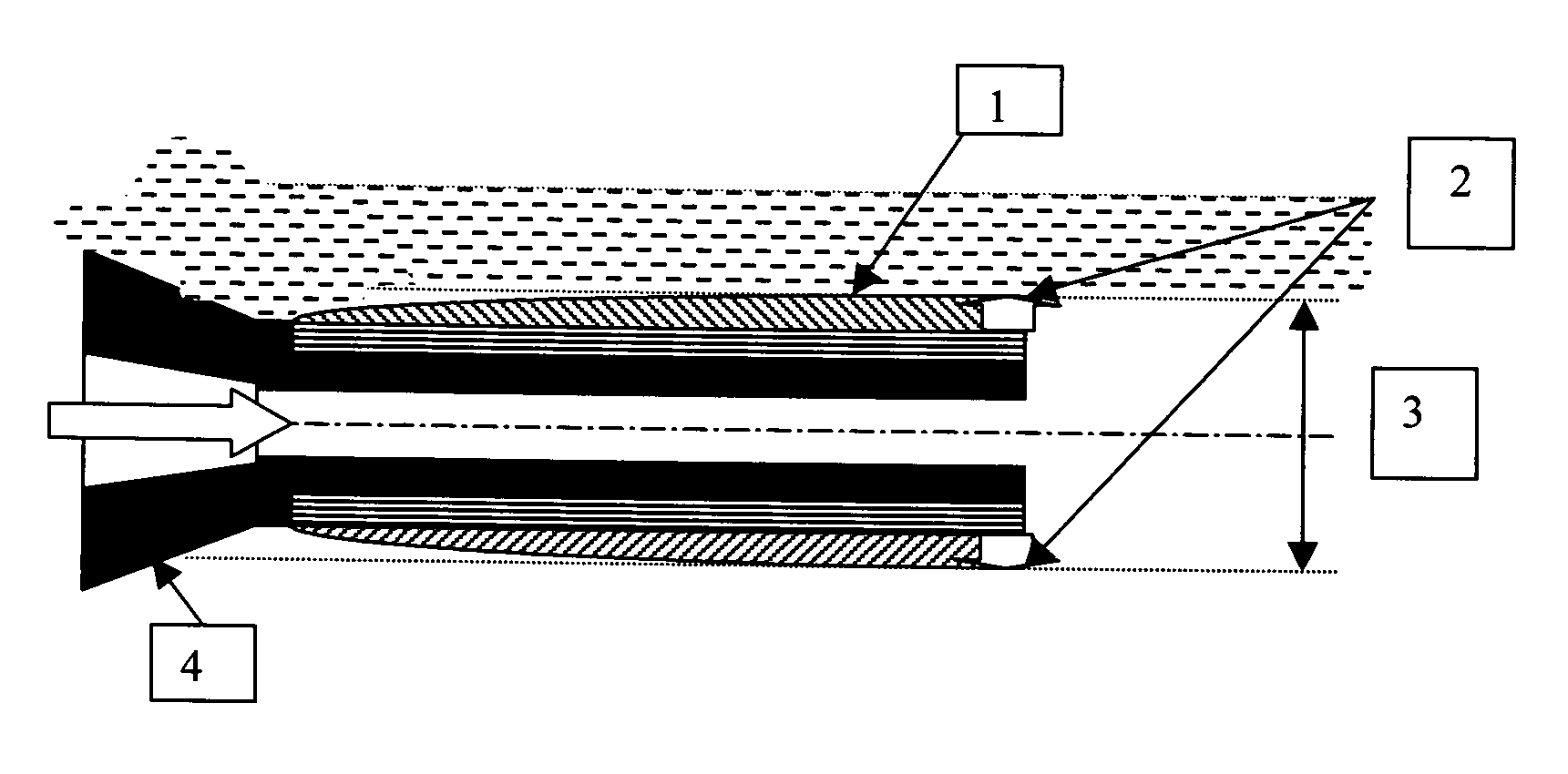
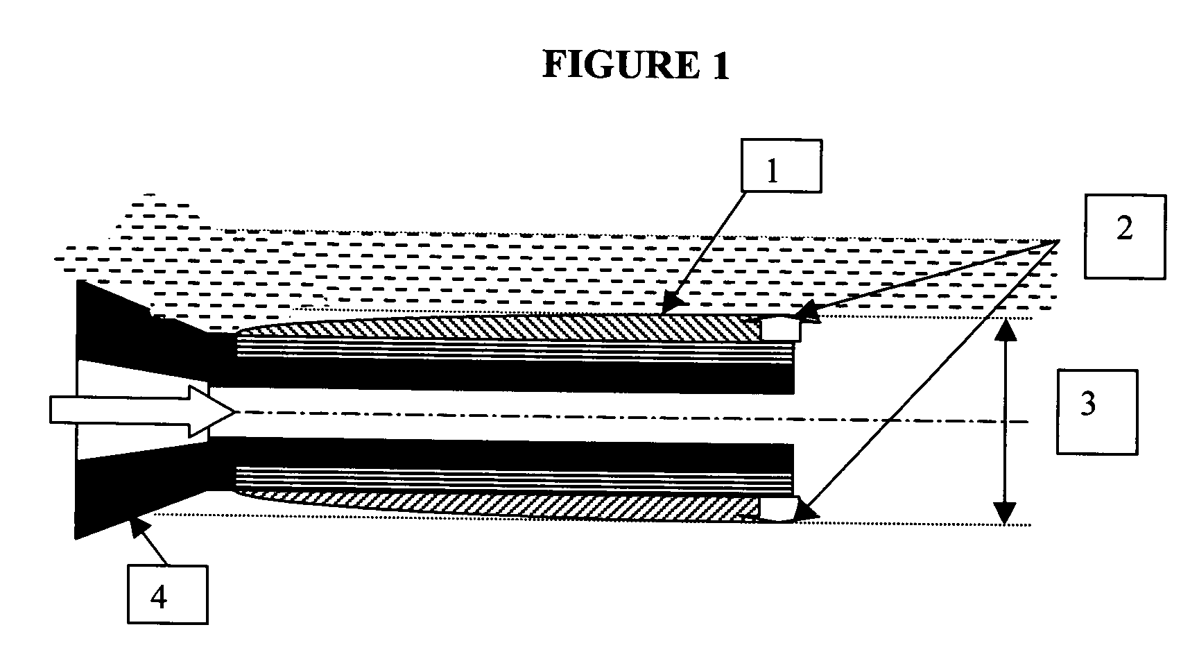
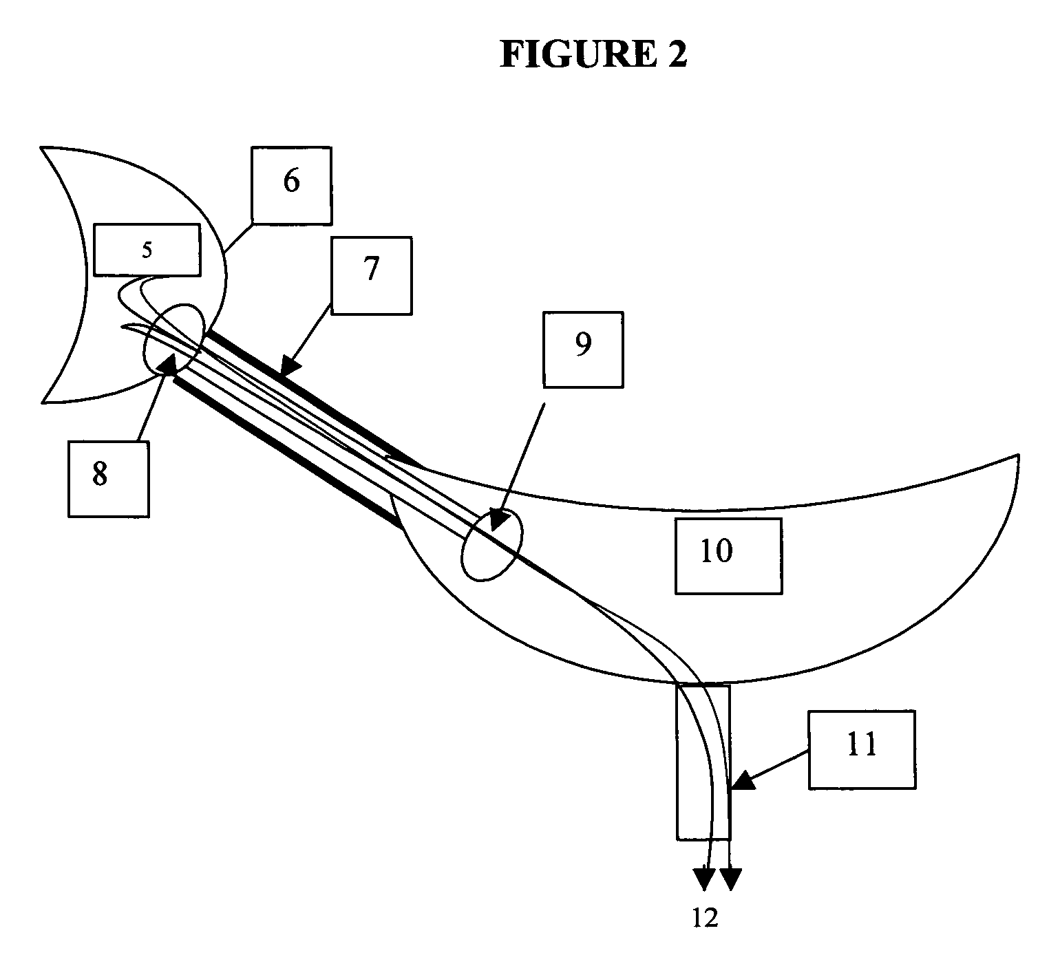
[0024] Referring now to the drawings, particularly in FIG. 1, there is generally indicated the stent of the present invention. As illustrated in FIG. 1, the body of the stent 1 is displayed, along with the uretral lumen 3 and the outward radial forces 2. The trumpet or barbell distal end for anchorage with radiopacifier fill 4 is also shown. In FIG. 2, the path urine travels through the body is shown. How the urine 5 will flow from the kidney, 6 through the anchorage in the kidney, 8 through the ureter, 7 through the anchorage of the ureter 9 and into the bladder 10. The urine will then flow 12 through ...


PUM

PropertyMeasurementUnit
Forceaaaaaaaaaa
Diameteraaaaaaaaaa
Electrical resistanceaaaaaaaaaa

Abstract

The present invention relates generally a manufacturing process which results in a completely hydrogel polymer device that maintains lumen patency which allows for numerous applications. Catheters and stents are particular examples, and their composition, mechanical characteristics, and the significantly unique ability to conduct and allow fluids to pass from one end to the other without physiological rejection, inflammation, or manifestation of complications due to implant or otherwise undesirable outcomes when used for ambulatory and or therapeutic interventions is the purpose of the invention.

Description

FIELD OF INVENTION [0001] The present invention relates generally to a manufacturing process and a resulting apparatus which results in a completely hydrogel polymer device that maintains lumen patency which allows for numerous applications, particularly, catheters and stents. BACKGROUND OF THE INVENTION [0002] Generally, the common approaches utilized in the art to fabricate a product from hydrolyzed PAN entail typically coagulating a single layer or heavily plasticizing a solvent based formula hydrolyzed PAN, in order that it may be molded or extruded by conventional thermoplastic extrusion or injection molding methods. Unfortunately, do to limitations, these materials and related processes are not reliable and often lead to inconsistencies in production and / or components. [0003] As referenced in U.S. Pat. No. 6,232,406 and in fact improvements so noted in U.S. Pat. No. 4,943,618 are probably not necessary when manufacturing a product with the disclosed process. Many types of devi...

Claims


Application Information

Patent Timeline
IPC IPC(8): A61F2/06A61F2/82
CPCA61F2/82A61F2/844A61L29/041A61L29/145A61L31/048A61L31/145A61M25/0017A61M2207/00
Inventor EPSTEIN, SCOTT
Owner EPSTEIN SCOTT
Learn More