LNG system with high pressure pre-cooling cycle

a technology of pre-cooling cycle and high-pressure, which is applied in the direction of lighting and heating equipment, refrigeration and liquidation, and solidification, etc. it can solve the problems of pipeline availability or capacity exceeding the deliverability of pipeline, pipelines that are not available or are impractical, and achieve high capacity, high capacity, and the effect of large equipment and/or piping

Inactive Publication Date: 2007-05-17
CONOCOPHILLIPS CO
View PDF10 Cites 7 Cited by
  • Summary
  • Abstract
  • Description
  • Claims
  • Application Information

AI Technical Summary

Benefits of technology

[0011] A further object of the invention is to provide a high capacity pre-cooling cycle for LNG facilities that does not require significantly larger equipment and / or piping than conventional propane pre-cooling cycles.
[0012] Another object ofthe invention is to provide a high capacity pre-cooling cycle for LNG facilities that does not require a refrigerant compressor of significantly larger capacity than conventional compressors employed in propane pre-cooling cycles.

Problems solved by technology

It is desirable to operate the pipeline under a substantially constant and high load factor but often the deliverability or capacity of the pipeline will exceed demand while at other times the demand may exceed the deliverability of the pipeline.
The liquefaction of natural gas is of even greater importance when transporting gas from a supply source which is separated by great distances from the candidate market and a pipeline either is not available or is impractical.
Ship transportation in the gaseous state is generally not practical because appreciable pressurization is required to significantly reduce the specific volume of the gas.
Such pressurization requires the use of more expensive storage containers.
As the demand for high capacity LNG facilities increases, conventional propane pre-cooling systems are becoming inadequate.
However, a number of disadvantages are associated with increasing the cooling capacity of a propane pre-cooling cycle by simply increasing the flow rate of propane through though the system.
For example, increasing the flow rate of the propane refrigerant in the pre-cooling cycle requires larger compressors and larger piping.
Obviously, the use of larger equipment and piping increases the cost ofthe facility.
Further, larger equipment and piping takes up more space—an undesirable feature when plot space is limited, such as for offshore LNG facilities.
In addition, the capacity of conventional propane refrigerant compressors is already at or near the limits of known technology.
Thus, procuring a propane compressor of significantly higher capacity than currently available propane compressors would be very expensive, if not impossible.

Method used


Image

  • LNG system with high pressure pre-cooling cycle
  • LNG system with high pressure pre-cooling cycle

Examples


Embodiment Construction

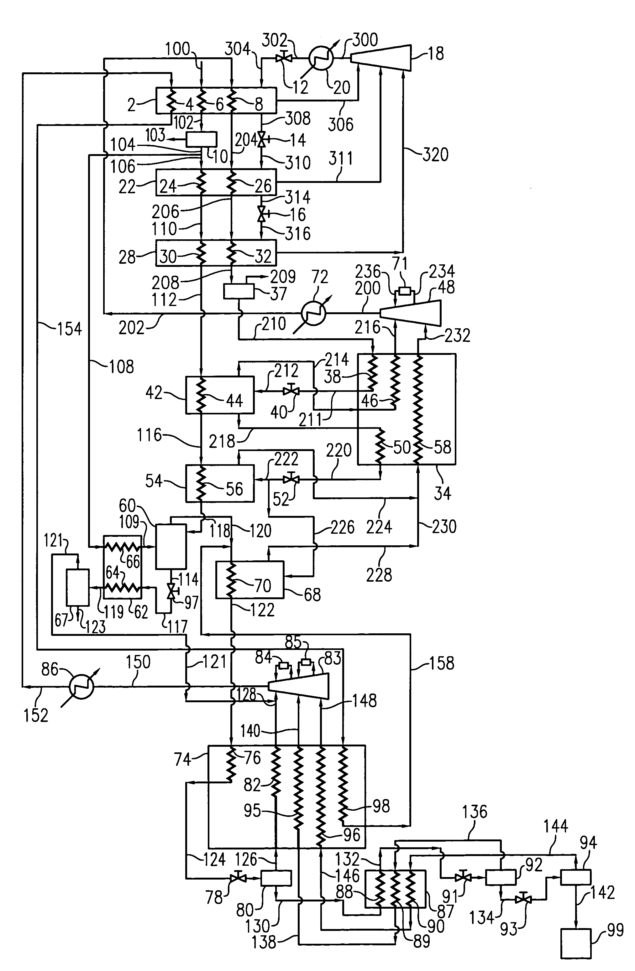
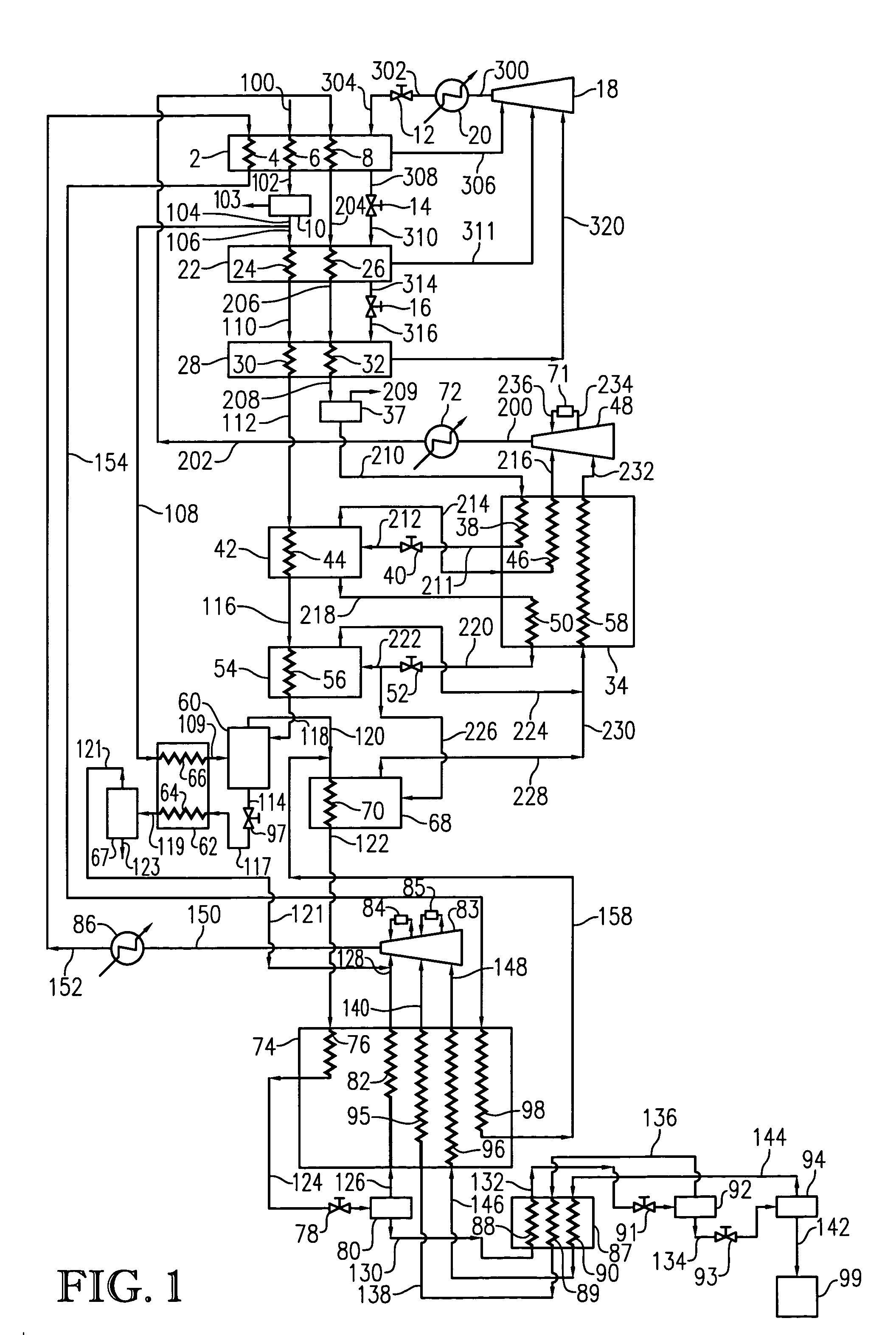
[0017] A cascaded refrigeration process uses one or more refrigerants to transfer heat from a natural gas stream to a refrigerant, and ultimately transferring the heat from the refrigerant to the environment. In essence, the overall refrigeration system functions as a heat pump by removing heat energy from the natural gas stream as the stream is progressively cooled to lower and lower temperatures. The design of a cascaded refrigeration process involves a balancing of thermodynamic efficiencies and capital costs. In heat transfer processes, thermodynamic irreversibilities are reduced as the temperature gradients between heating and cooling fluids become smaller, but obtaining such small temperature gradients generally requires significant increases in the amount of heat transfer area, major modifications to various process equipment, and the proper selection of flow rates through such equipment so as to ensure that both flow rates and approach and outlet temperatures are compatible ...


PUM


Abstract

A natural gas liquefaction system employing a high pressure pre-cooling refrigeration cycle.

Description

BACKGROUND OF THE INVENTION [0001] 1. Field of the Invention [0002] This invention relates to a method and apparatus for liquefying natural gas. In another aspect, the invention concerns an improved liquified natural gas (LNG) facility employing a high pressure pre-cooling cycle. [0003] 2. Description of the Prior Art [0004] The cryogenic liquefaction of natural gas is routinely practiced as a means of converting natural gas into a more convenient form for transportation and storage. Such liquefaction reduces the volume of the natural gas by about 600-fold and results in a product which can be stored and transported at near atmospheric pressure. [0005] Natural gas is frequently transported by pipeline from the supply source to a distant market. It is desirable to operate the pipeline under a substantially constant and high load factor but often the deliverability or capacity of the pipeline will exceed demand while at other times the demand may exceed the deliverability of the pipel...

Claims


Application Information

Patent Timeline
Patent Type & Authority Applications(United States)
IPC IPC(8): F25J1/00
CPCF25J1/0022F25J1/021F25J1/0254F25J1/0292F25J1/0087F25J2245/02F25J1/004F25J1/0052F25J1/0085F25J2220/64
Inventor RANSBARGER, WELDON L.
Owner CONOCOPHILLIPS CO
Why Eureka
Try Eureka