Bottle filling machine with sensor and method thereof

a technology of a filling machine and a sensor, which is applied in the direction of liquid handling, instruments, packaged goods, etc., can solve the problems of increased labor, increased costs, and inconvenient filling levels,

Inactive Publication Date: 2007-05-17
SIDEL PARTICIPATIONS SAS +1
View PDF6 Cites 92 Cited by
  • Summary
  • Abstract
  • Description
  • Claims
  • Application Information

AI Technical Summary

Benefits of technology

[0020] An additional feature of the present invention reduces an occurrence of a single anomaly that causes an incorrect valve setting change. This is accomplished by looking at a statistically significant number of measurements before a change is made in a timing recipe or a fi

Problems solved by technology

However, such a cam arrangement is susceptible to various types of mechanical wear and misadjustment leading to inaccurate or inconsistent filling levels.
In addition, a skilled technician is needed to adjust, maintain, and calibrate a substantial number of cam operated devices, which can result in increased costs, lower productivity, and increased labor.
Stopping to make such mechanical adjustments or to change to a new filling job also contributes to additional down-time on the filling line, which is very expensive in terms of lost production.
Because the flow sensors are relatively expensive, it becomes a substantial expense to build machines that have the same number of costly flow sensors as filling valves.
However, this process requires a complex, close integration between the camera's findings and the valve control electronics to effect a precise shut-off.
In addition, because the camera is actually viewing the containers as they are being filled, turbulence is induced during the imaging period.
If the turbulence is not consistent or the system is lacking a mea

Method used


Image

  • Bottle filling machine with sensor and method thereof
  • Bottle filling machine with sensor and method thereof
  • Bottle filling machine with sensor and method thereof

Examples


Embodiment Construction

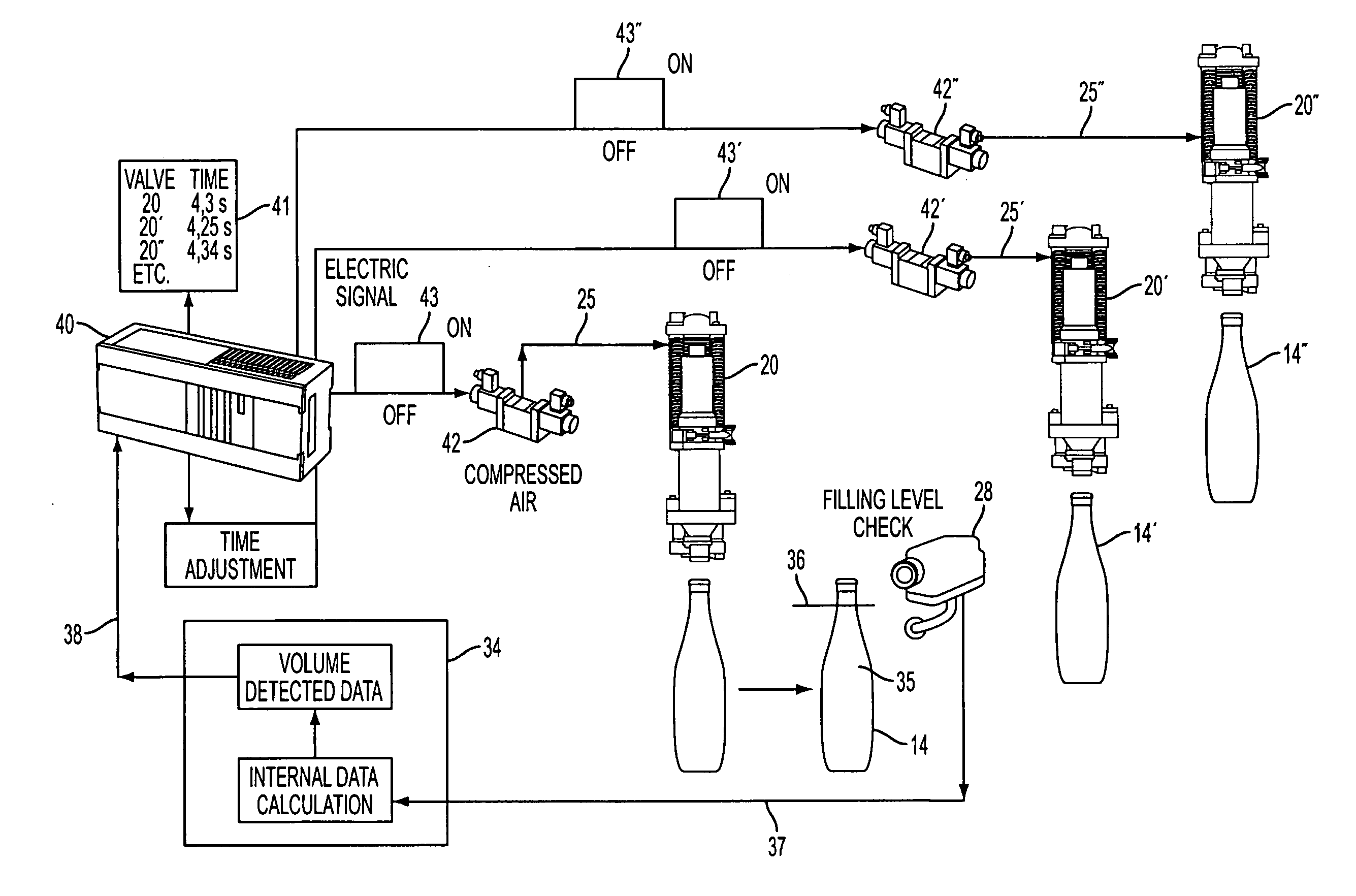
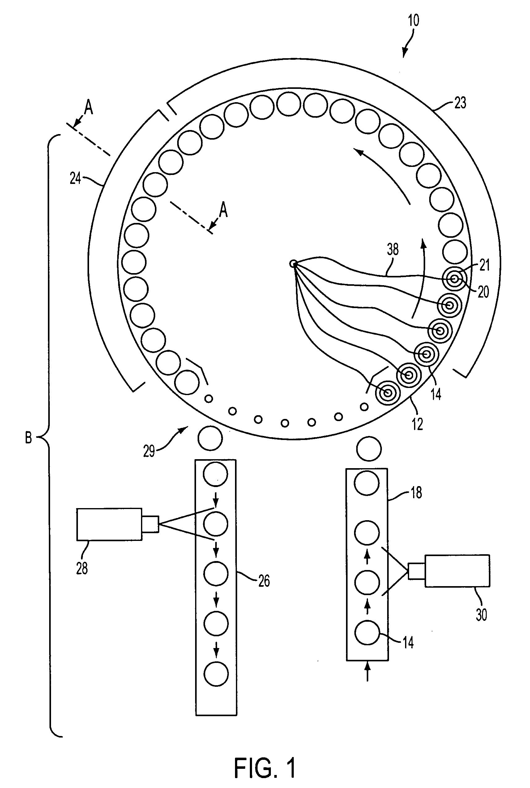
[0030]FIG. 1 is a top view of a filling machine 10 having a rotatable carrier or carousel 12 for transporting containers 14. A wide variety of containers may be used in the present apparatuses and methods, such as glass, plastic, metal, paperboard or the like. For example, the apparatuses and methods may be used to measure liquids or granular solid materials, such as fine chemicals, pharmaceuticals or foodstuffs, or materials comprising solids suspended in liquids. The containers themselves can also vary widely in size and shape and may have the form of, for example, drums, carboys, flasks, cartons, jars, cans, and bottles. However, an exemplary embodiment of the present invention is intended for use with containers containing liquids and, accordingly, the detailed description of the processes hereinafter will mainly be with reference to such bottles of liquid, since the necessary modifications of the apparatus and method for use with other types of containers and contents will be r...


PUM

PropertyMeasurementUnit
Temperatureaaaaaaaaaa
Weightaaaaaaaaaa
Timeaaaaaaaaaa

Abstract

A filling apparatus and method including a carrier for transporting containers and having a plurality of valves, each of the valves being opened for an individual, specific period of time to control a flow of liquid into the respective containers, while the containers are transported by the carrier. An exit feed path transports the containers after the containers have been filled, and a sensor, such as a camera, detects a level of liquid in the respective containers, while the containers are on the exit feed path. The sensor produces a signal that is stored as data representing the level of liquid for the individual containers. The data is then tracked and used for valve optimization. A period of time that each individual valve is opened for subsequent fillings is adjusted based on the signal and the historical performance of each valve.

Description

BACKGROUND OF THE INVENTION [0001] 1. Field of the Invention [0002] Apparatuses and methods consistent with the present invention relate generally to regulating the dispersion of liquid into a container. More specifically, the invention relates to detecting a level of the liquid in the container, so as to obtain data and appropriately adjust a valve used to regulate the flow of the liquid. [0003] 2. Description of the Related Art [0004] In general, the bottling of beverages, sauces, liquid spices, etc., requires adjusting the bottling amount within a predetermined range. For example, it is known to regulate an amount of flow into a container using cam actuated filling valves, wherein containers are conveyed along circular path on a carrier, while being filled via nozzles that direct fluid or other material contents downwardly into the containers. In such a configuration, a carousel rotates to move the nozzles synchronously with the passing containers and the cam moves the nozzles do...

Claims


Application Information

Patent Timeline
IPC IPC(8): B65B43/42
CPCB65B3/36B65B57/145B67C3/007G01F13/006G01F23/20G01F23/292
Inventor COCHRAN, DON W.SCHIANCHI, ROBERTOMUTTI, FRANCOLUPI, ANDREA
Owner SIDEL PARTICIPATIONS SAS
Why Eureka
Try Eureka