

Tape pressure roller with patterned surface for tape applicator
a pressure roller and tape applicator technology, applied in the direction of paper hanging, walls, transportation and packaging, etc., can solve the problems of high application cost, high application cost, irregular or uneven roof surface, etc., and achieve the effect of reducing the application force of users
- Summary
- Abstract
- Description
- Claims
- Application Information
AI Technical Summary
Benefits of technology
Problems solved by technology
Method used
Image

Examples
example
Example 1
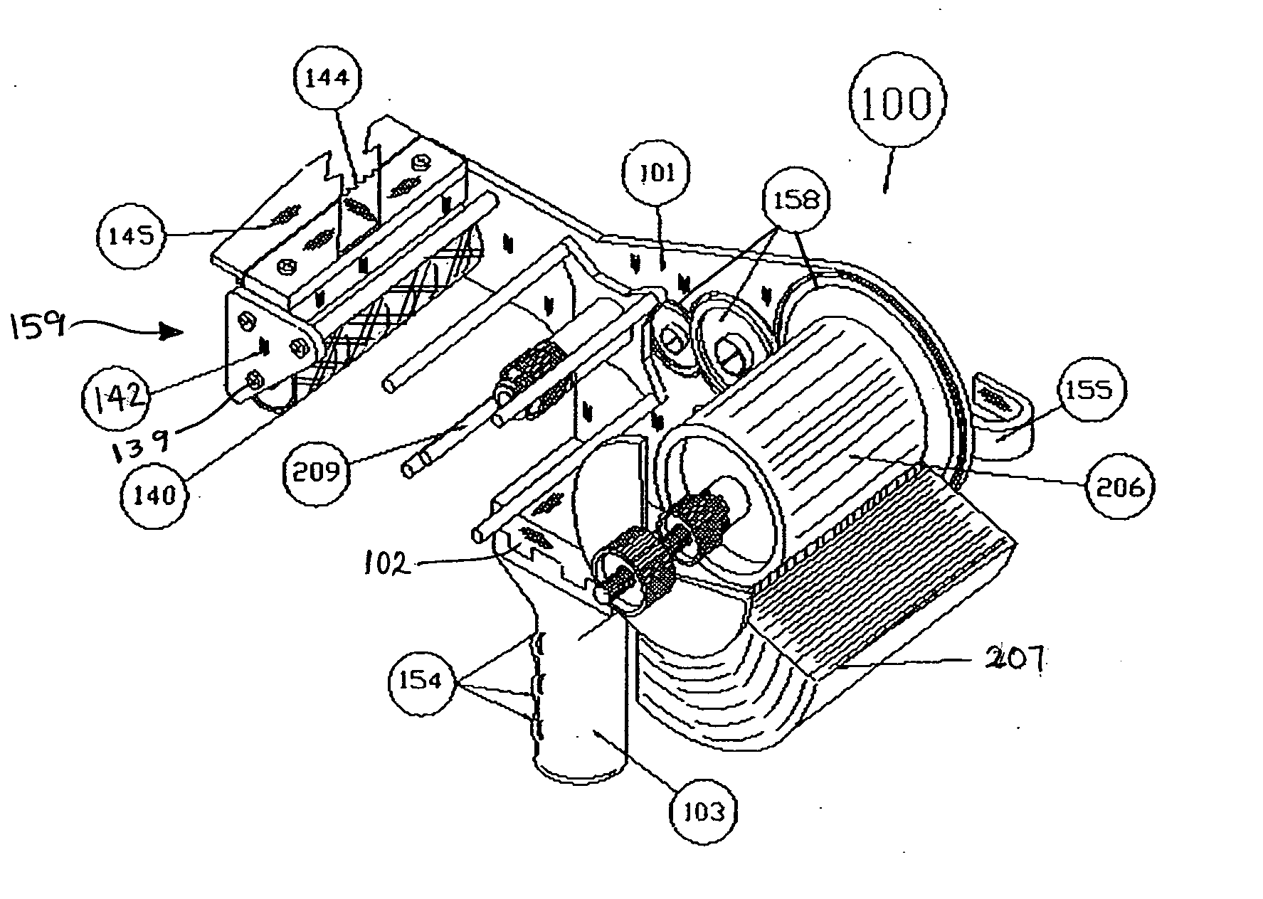
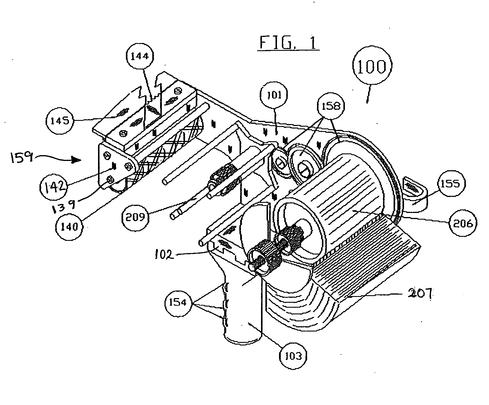
[0064] Water penetration tests were performed on panels seamed panels using a tape applicator equipped with one of several different patterned pressure rollers representative of embodiments of the present invention and several control rollers in the following manner. The tape applicator device was of the type described in FIGS. 1, 6-8 herein. In this testing, the tape was applied at ambient temperatures of approximately 80-90° F. Each specimen roller pattern was tested twice with the same tape.
[0065] Test protocol used: 1) Cut 2 inch×4 inch studs and nailed them together to form a 24 inch×24 inch frame including a central stud. 2) Cut one panel of an OSB substrate to dimensions of 12 inch×24 inch, laid it on top of the frame with the panel edges oriented perpendicular to and overlying the central stud, and nailed the panel to the surface of the frame. One half of the frame was covered with panel, and the other half was still exposed at this juncture. 3) Cut two panels of ...
example 2
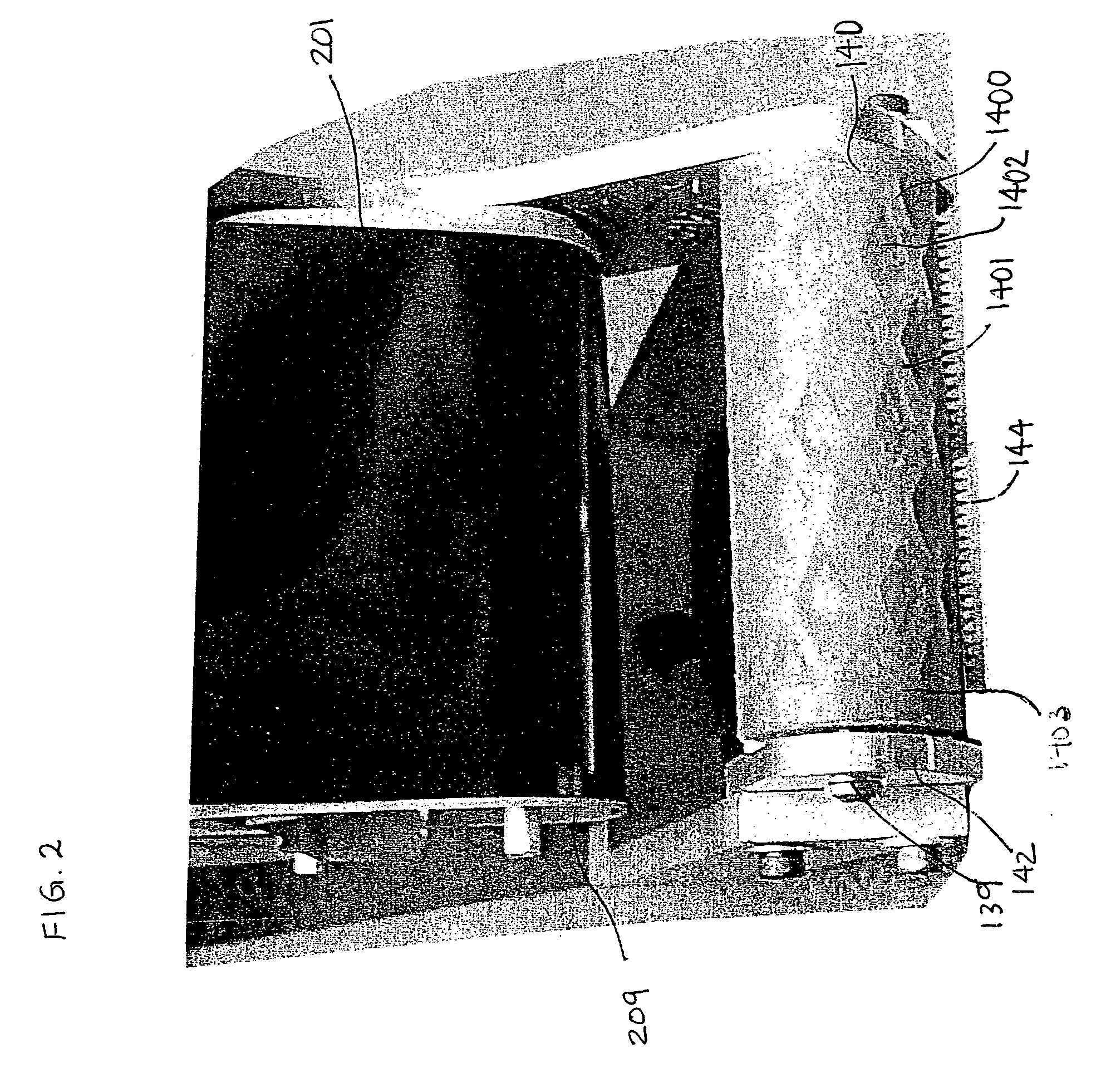
[0070] A tape applicator was used to apply commercial Zip™ tape over the seams of abutting sheathing panels on a roof. The sheathing panels had an overlay of resin-impregnated Kraft paper and a texture had been embossed into the surface of the overlaid sheathing panel. The texture had a pattern that generally runs in two directions; one along the length of the panel and the second along the width of the panel. The tape applicator was of the type described in FIGS. 1, 6-8 herein and was equipped with a patterned pressure roller (1.5 inch diameter) having diamond shapes cut into its outer peripheral surface generally according to FIG. 2 (average upraised line width of about 0.138 inch; 45 degree angle; 3 diamonds / inch vertical; 2.5 diamonds / inch horizontal; 30 Durometer).
[0071] An excellent water tight seal was provided that was able to pass, with a single pass of the pressure roller over the tape at an application pressure of 4.25 pound force, the ASTM E331-00 “Standard Test Method ...
example 3
[0072] Another water penetration test was performed on seamed panels in compliance with the ASTM E331-00 Standard Test Method, albeit with a smaller test chamber than the one used in Example 2. The tape applicator device was the same as that described in Example 2.
[0073] Summary of Test Method: This test method consisted of sealing the test specimen into one face of a test chamber, exhausting air from the chamber at the rate required to maintain the test pressure difference across the specimen, while spraying water onto the outdoor face of the specimen at the required rate and observing any water penetration.
[0074] Apparatus: The description below of apparatus used is general in nature.
[0075] Test Chamber: A test chamber or box with an opening in which a removable mounting frame was installed with the specimen installed on the frame. One static pressure tap was provided to measure the chamber pressure. The back of the chamber consisted of a glass plate. The user sat under the gla...
PUM
| Property | Measurement | Unit |
|---|---|---|
| weight | aaaaa | aaaaa |
| diameter | aaaaa | aaaaa |
| width | aaaaa | aaaaa |
Abstract
Description
Claims
Application Information