

Flat plate heat transfer device
- Summary
- Abstract
- Description
- Claims
- Application Information
AI Technical Summary
Benefits of technology
Problems solved by technology
Method used
Image

Examples
experiment 1
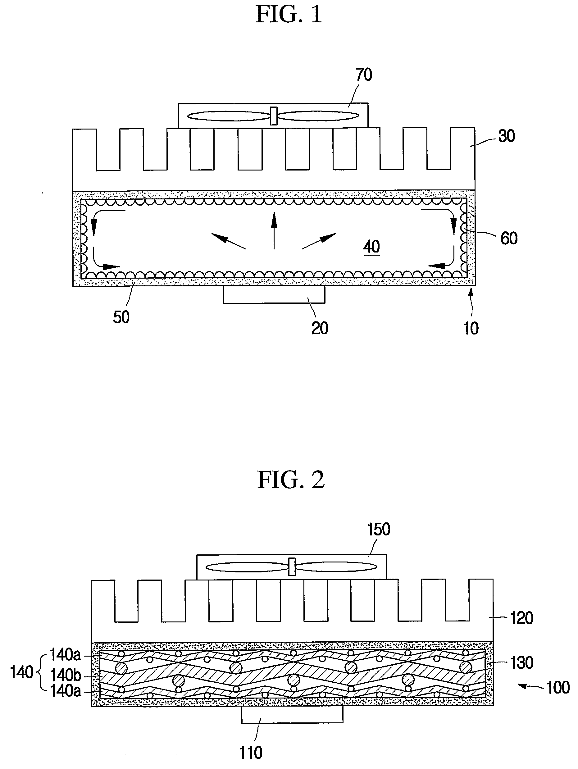
[0085] A screen mesh made of copper was selected for the coarse mesh layer in each case of the following Table 1. In addition, a screen mesh made of copper and having a mesh number of 100 and a mesh wire diameter of 0.11 mm was selected for the fine mesh layer. After that, 11 mesh layer aggregates were configured with a structure as shown in FIG. 2.
TABLE 1CaseWire diameter [mm]Mesh number [# / inch]R [° C. / W]10.20150.7020.20240.7430.2050∞40.35100.6750.35120.6360.35140.6170.35160.6580.35180.6790.3530∞100.48100.78110.718∞
[0086] Subsequently, the plurality of mesh layer aggregates were mounted between upper and lower flat cases (see FIG. 14), and the flat cases were sealed by means of denatured acrylic binary bond (HARDLOCTH, made by DENKA in Japan) with leaving a working fluid injection hole. At this time, an oxide free copper plate with a thickness of 0.2 mm was used for the flat case, and the flat case was 80 mm in length and 70 mm in width.
[0087] After the flat case was sealed as ...
experiment 2
[0098] The inventors made a flat plate heat transfer device (hereinafter, referred to as a sample 1) with a length of 150 mm, a width of 50 mm and a height of 2.25 mm in order to check an effect of the flat plate heat transfer device according to the present invention. The flat case is configured by combining upper and lower flat cases that are separately prepared, and it is made of copper foil with a thickness of 0.1 mm.
[0099] A mesh layer aggregate to be mounted in the flat case is laminated as shown in FIG. 7 with the use of copper screen meshes in which a content of copper is at least 99%. A coarse mesh layer uses a screen mesh made of copper and in which a wire diameter is 0.35 mm, a layer thickness is 0.74 mm and a mesh number is 14. In addition, a fine mesh layer uses a screen mesh made of copper and in which a wire diameter is 0.11 mm, a layer thickness is 0.24 mm and a mesh number is 100.
[0100] In order to make the sample 1 to be used in this experiment, the mesh layer ag...
PUM
 Abstract
Description
Claims
Application Information