
Method and device for measuring and correcting aberrations of eye

Inactive Publication Date: 2007-05-17
IND TECH RES INST
View PDF5 Cites 31 Cited by
  • Summary
  • Abstract
  • Description
  • Claims
  • Application Information

AI Technical Summary

Benefits of technology

[0011] Another objective of the present invention is to provide an eye aberration measuring and correcting device and a method thereof such that optometric testing and wavefront testing are configured as aplanatic structures to enhance the accuracy of the optometric testing.
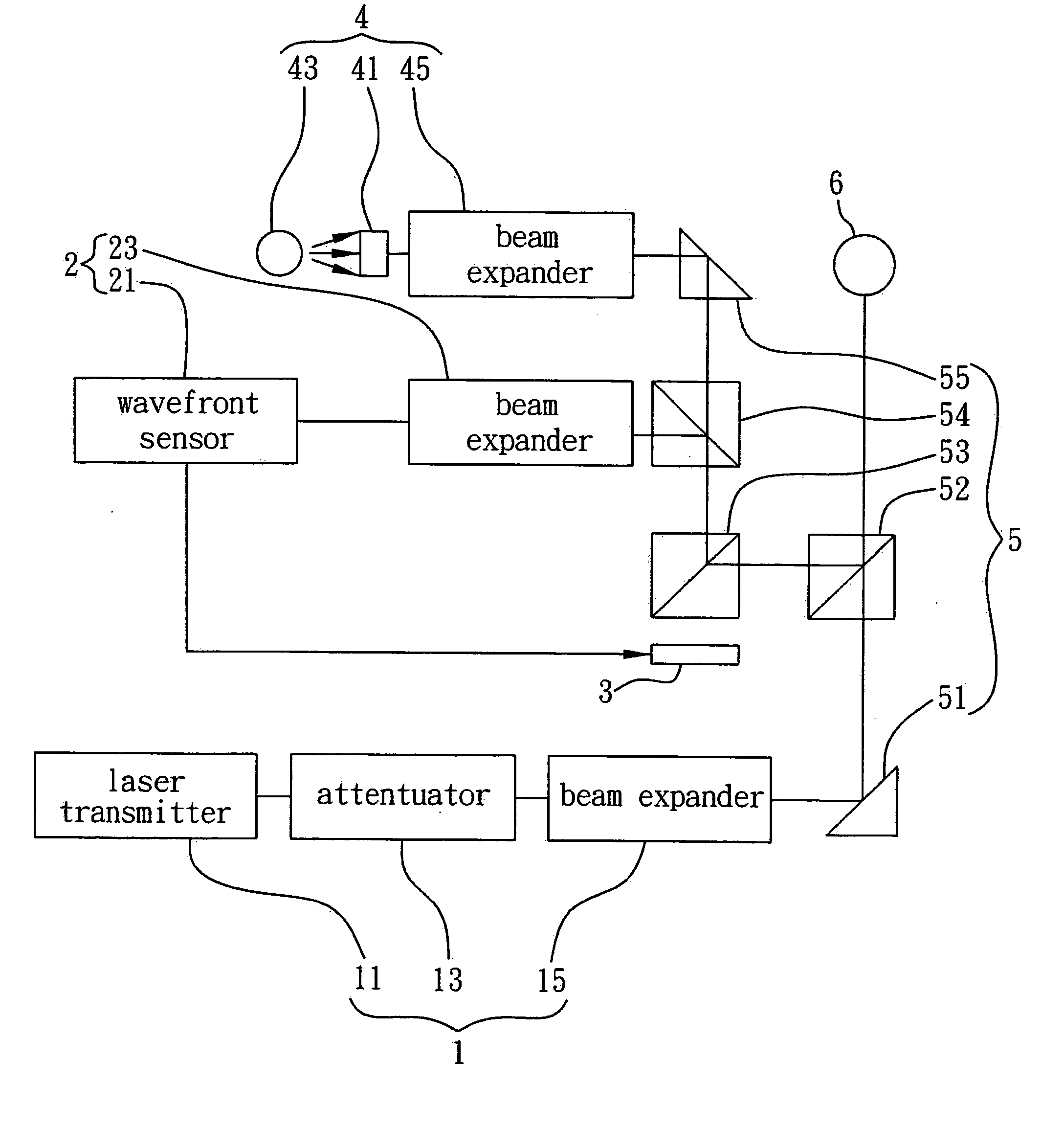
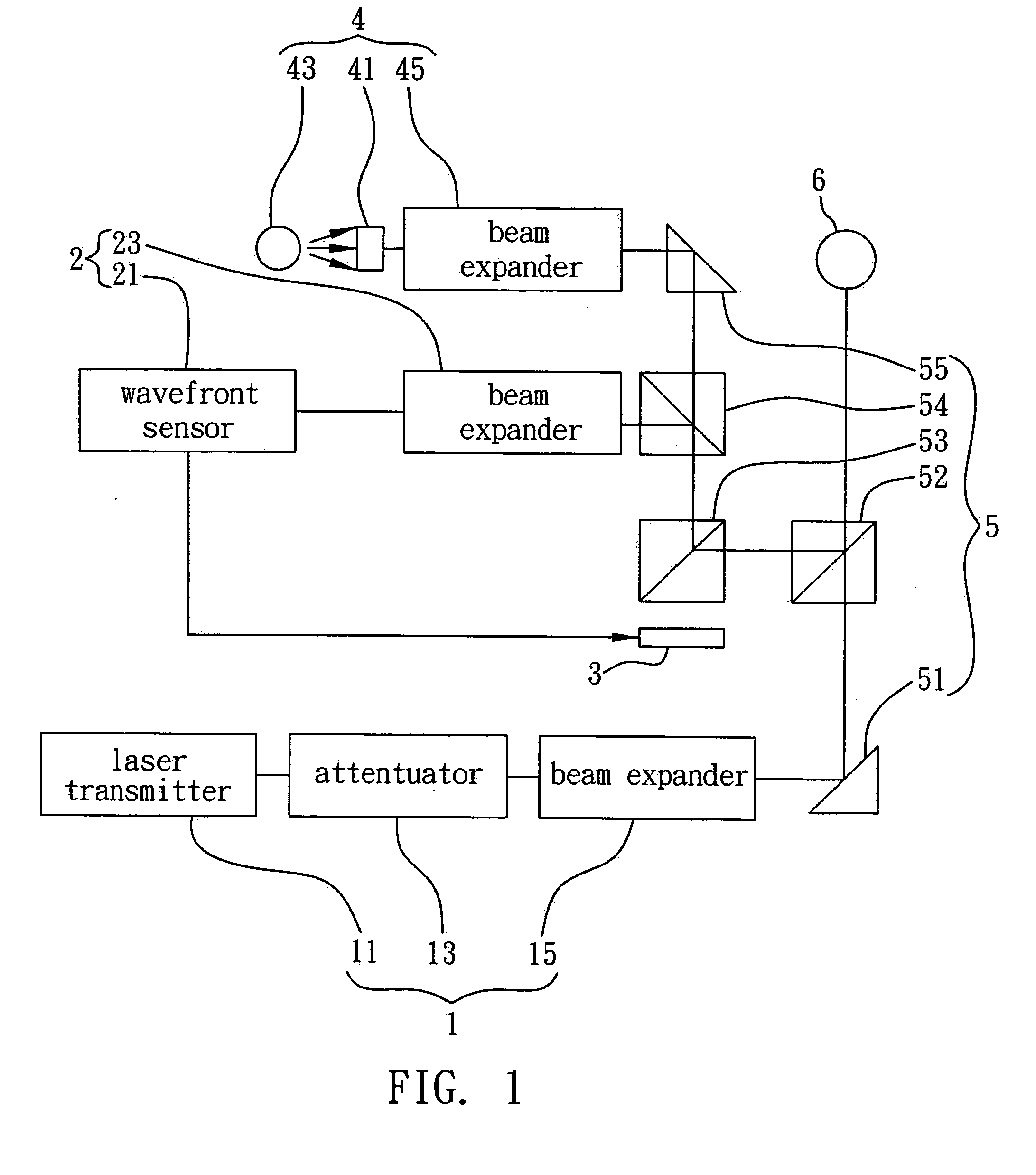
[0014] As regards the aforementioned device, the laser unit may include a laser transmitter, an attenuator and a beam expander. In another embodiment, the laser unit may further include an on-and-off controller for controlling the laser unit so as to allow the laser unit to switch properly between an on state and an off state, thus reducing the time for which the eye is irradiated by laser. The wavefront sensing unit may include a wavefront sensor and a beam expander. The wavefront sensor may include an array of microlenses and an image sensor.
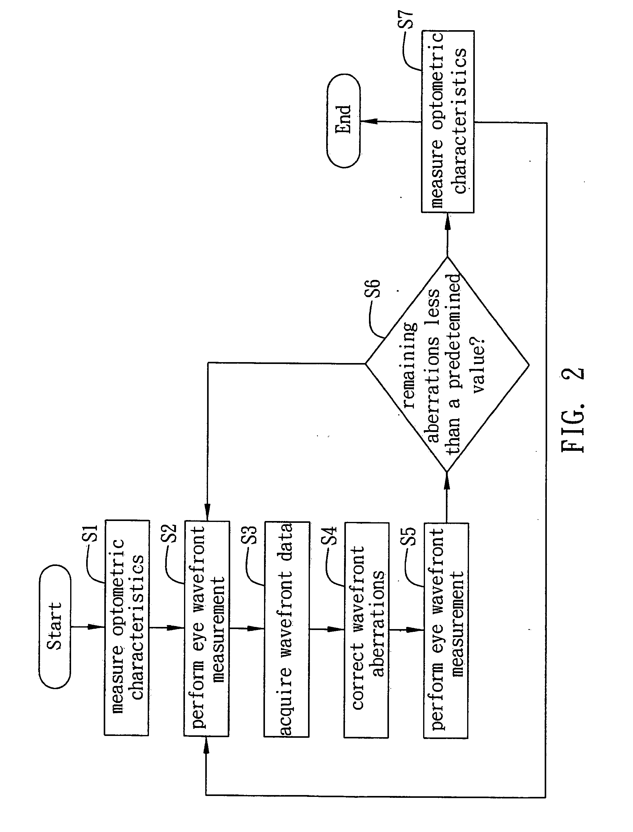
[0021] The device and method for measuring and correcting eye aberrations of the present invention allow wavefront sensing, wavefront aberration correction, and optometric testing to be integrated with each other, and allow the optical paths of wavefront sensing and optometric testing to be configured as aplanatic structures, such that under optometric testing conditions both wavefront sensing and aberration correction can be performed simultaneously, and final optometric testing can be conducted on wavefront aberration-corrected optometric parameters to verify if the wavefront aberration-corrected optometric parameters fall within normal visual range, thus ensuring the accuracy and high repetition of the measured optometric parameters, which provides accurate reference data for laser ophthalmic surgery, and design and fabrication of the device can be simplified. Therefore, the present invention solves the various shortcomings of the prior art.

Problems solved by technology

Upon entry of parallel light into the eye with aberrations, the wavefront of the light reflected from the retina may be distorted due to irregular structures of the eye, causing images to be blurred, scattered, dragged and etc.
However, such elements do have their own disadvantages, namely bulky and expensive, thus failing to meet the need for miniaturization and popularity of the eye aberration measuring devices.
However, this kind of wavefront measuring device does not optimize measurement and correction, resulting in great uncertainty of aberration measurement.
In addition, a target object seen by an eye undergoing measurement and the optical path of the measuring device are independent of each other, and thus the difference of optometric parameters before and after aberration correction cannot be accurately determined.
However, for a person with higher-order aberrations, even if s / he regains a visual acuity of 1.0 to 1.2 after the laser surgery, the remaining 15% higher-order aberrations will remain unsolved, and thus s / he may still experience pro-operational sequelae, such as halo, glare, dazzle, and diplopia.
Wavefront aberration analysis is presently designed to evaluate eyesight only and has disadvantages, such as low repetition of measurement and inconsistent measurement results between different brands of instruments; in consequence ophthalmic surgeons resort to clinic experience instead of instrument-generated data, thus increasing the risks of surgery.
Furthermore, pre-operational and post-operational visional changes cannot be assessed by means of wavefront measuring devices nowadays, thus increasing the uncertainty of the aforesaid surgery.

Method used


Image

  • Method and device for measuring and correcting aberrations of eye
  • Method and device for measuring and correcting aberrations of eye
  • Method and device for measuring and correcting aberrations of eye

Examples


Embodiment Construction

[0025] The present invention is described by the following specific embodiments. Those with ordinary skills in the art can readily understand the other advantages and functions of the present invention after reading the disclosure of this specification. The present invention can also be implemented with different embodiments. Various details described in this specification can be modified based on different viewpoints and applications without departing from the scope of the present invention.

[0026] It should be noted that the accompanying drawings are simplified in order to illustrate the basic structure of the present invention. Thus, only those elements related to the present invention are shown in the diagrams. The shown elements may not be drawn according to actual quantity, shape and size, which are only a matter of design choices. The layout of the elements may be more complicated than that shown.

[0027]FIG. 1 is a block diagram showing an eye aberration measuring and correct...


PUM


Abstract

A device and method for measuring and correcting eye aberrations integrate wavefront sensing, wavefront aberration correction and optometric testing into one another and configure the optical paths of wavefront sensing and optometric testing as aplanatic structures, such that under optometric testing conditions both wavefront sensing and aberration correction can be performed simultaneously, and final optometric testing is conducted on wavefront aberration-corrected optometric parameters to verify if the wavefront aberration-corrected optometric parameters fall within normal visual range, thus ensuring the accuracy and high repetition of the measured optometric parameters.

Description

FIELD OF THE INVENTION [0001] The present invention is related to a method and device for measuring and correcting aberrations of an eye, more specifically, a method and device for measuring and correcting aberrations of an eye before / during / after laser ophthalmic surgery. BACKGROUND [0002] Wavefront technique developed by the National Aeronautics and Space Administration (NASA) was initially applied in the field of space technology. Astronomers use wavefront analysis to process aberrations produced by the atmosphere in order to obtain relatively accurate data and images of the Galaxy. At present, this epochal technique is applied in the field of human vision measurement. Light entering the eye has to pass through several structures before arriving eventually at the retina to form visual images. However, refractive index and structure of the eye varies. Shapes of these structures also affect the propagation path of light entering the eye. Due to these and other factors, the so-calle...

Claims


Application Information

Patent Timeline
IPC IPC(8): A61B3/10
CPCA61B3/14
Inventor CHANG, CHUAN-CHUNGCHANG, CHENG-JONG
Owner IND TECH RES INST
Learn More