Exposure method and device manufacturing method, exposure apparatus, and program

a manufacturing method and exposure technology, applied in the field of exposure methods and device manufacturing methods, exposure apparatuses, programs, can solve the problems of difficult wafer alignment by the ega method, overlay error generation, overlay error generation, etc., and achieve good overlay precision, high throughput, and good overlay precision.

Active Publication Date: 2007-05-17
NIKON CORP
View PDF18 Cites 28 Cited by
  • Summary
  • Abstract
  • Description
  • Claims
  • Application Information

AI Technical Summary

Benefits of technology

[0031] When exposing each of a plurality of divided areas, the control unit controls a position of the photosensitive object via the moving body based on the estimate value of positional information of each divided area and the correction information that is latest. As a consequence, a position control of the photosensitive object (the moving body) on exposure is performed with good precision.
[0032] Accordingly, when continuously or intermittently exposing each of a plurality of photosensitive objects, exposure with high throughput and good overlay precision can be performed.

Problems solved by technology

In such a case, since a grid error of a stage between exposure apparatuses (an error between stage coordinate systems that define a moving position of a wafer in the exposure apparatuses) exists, an overlay error is generated.
In addition, even in the case of having no grid error of a stage between exposure apparatuses or in the case of using the same exposure apparatus, in the overlay between respective layers to which process processing steps such as etching, CVD (Chemical Vapor Deposition) or CMP (Chemical Mechanical Polishing) are performed, an overlay error may be generated at times because the process steps give distortion of an arrangement of shot areas.
However, when the arrangement error variation of shot areas is a non-linear component, it is difficult to remove it by the wafer alignment by the EGA method.
While an arrangement deviation of each shot area on the wafer hardly varies with respect to each lot, it is considered that how often and how the arrangement deviation varies depends on various factors such as an environment where the apparatus is placed, or an exposure process or its combination, and therefore, it is difficult to predict that.
Thus, as disclosed in Patent Document 2, when positional information of all shot areas on a wafer at the head of each lot is measured in actual, as a consequence it takes excessive time to measure the positional information of all shot areas, which decrease throughput more than it should be.
Therefore, it is hard to say that a method, in which positional information of all shot areas on a wafer at the head of the lot is measured in actual, is efficient.

Method used


Image

  • Exposure method and device manufacturing method, exposure apparatus, and program
  • Exposure method and device manufacturing method, exposure apparatus, and program
  • Exposure method and device manufacturing method, exposure apparatus, and program

Examples


Embodiment Construction

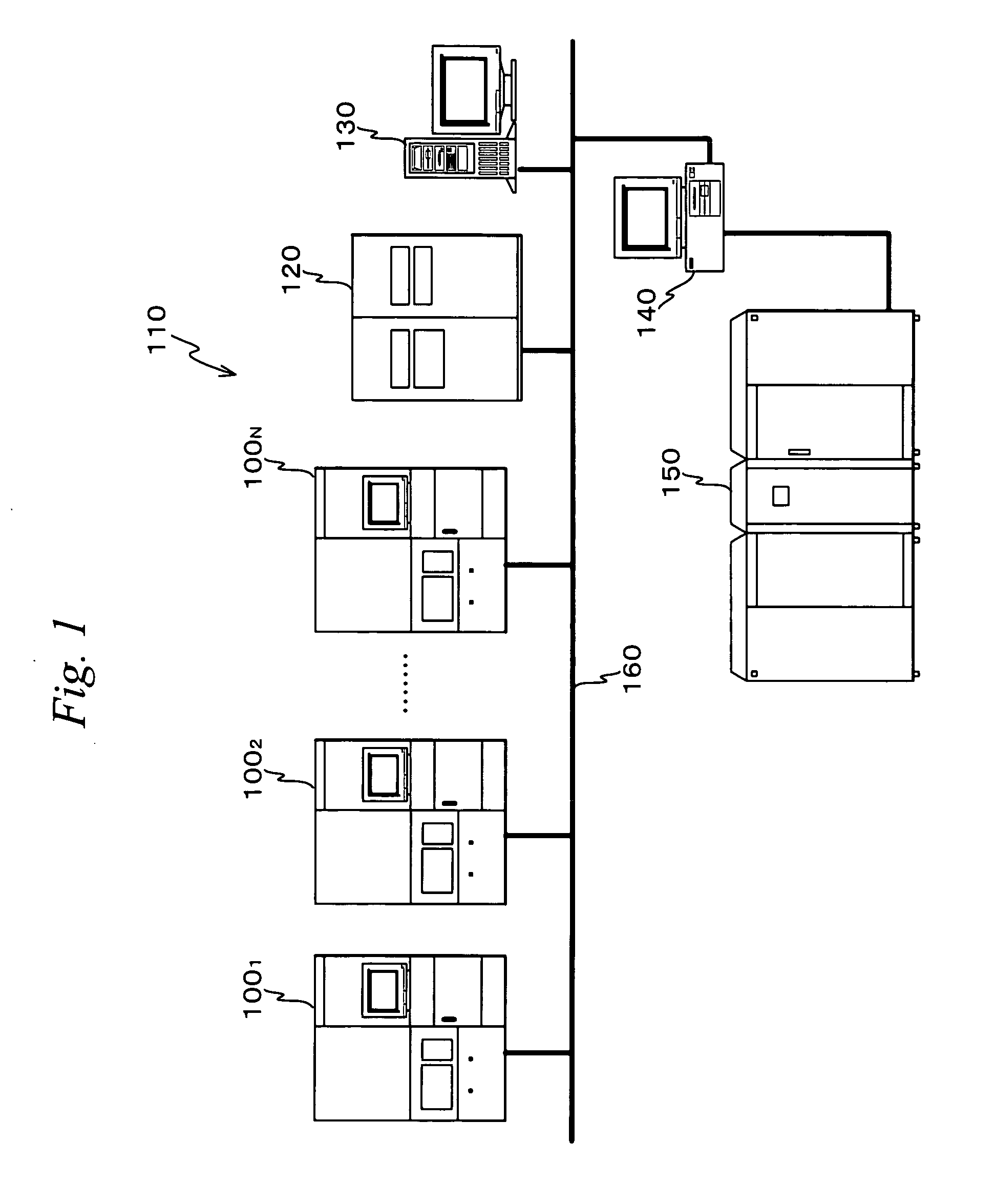
[0062]FIG. 1 schematically shows the entire configuration of a lithography system 110 in an embodiment of the present invention.

[0063] Lithography system 100 is equipped with N numbers of exposure apparatuses 1001, 1002, . . . , 100N, an overlay measuring instrument 120, a central information server 130, a terminal server 140, a host computer 150, and the like. Exposure apparatus 1001 to 100N, overlay measuring instrument 120, central information server 130 and terminal server 140 are connected to one another via local area network (LAN) 160. And, host computer 150 is connected to LAN160 via terminal server 140. That is, in terms of a hardware configuration, communication routes between exposure apparatus 100i (i=1 to N), overlay measuring instrument 120, central information server 130, terminal server 140, and a host computer 150 are secured.

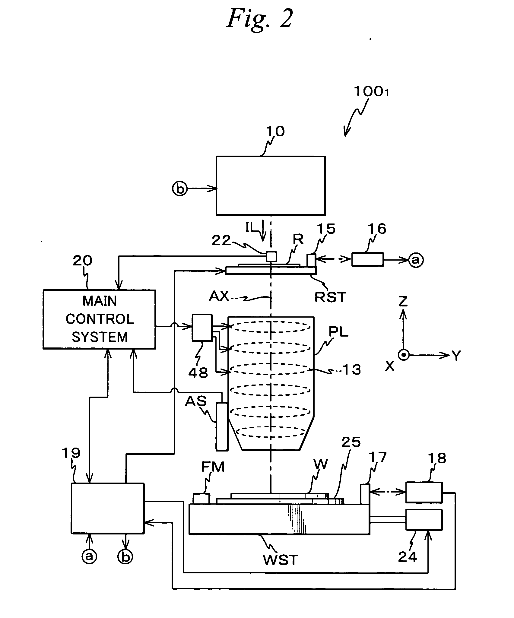
[0064] Each of exposure apparatuses 1001 to 100N may be a projection exposure apparatus by the step-and-repeat-method (so-called a ‘stepper’...


PUM

PropertyMeasurementUnit
wavelengthaaaaaaaaaa

Abstract

Positional information (an estimate value in which a linear component of positional deviation amount is corrected) of each shot on a wafer is calculated by a statistical computation using actual measurement values of positional information of a plurality of sample shots on the wafer (step 488). And, a variation amount of a non-linear component of positional deviation amount is calculated at predetermined intervals with respect to each of a plurality of measurement shots including the sample shots (step 496), and judgment is made about the necessity of update of correction information based on magnitude of the calculated variation amount of a non-linear component of each measurement shot area (step 498). Therefore, comparing with the case when actual values of positional information of all shots on the wafer are obtained at least once in each lot in order to update a correction value, the number of shots subject to positional information measurement and the measurement time can be reduced without fail.

Description

TECHNICAL FIELD [0001] The present invention relates to exposure methods and device manufacturing methods, exposure apparatuses, and programs, and more particularly to an exposure method in which an exposure processing of a specific process is continuously or intermittently performed to each of a plurality of photosensitive objects and a device manufacturing method that uses the exposure method, an exposure apparatus suitable to implement the exposure method, and a program suitable to make a computer for control of the exposure apparatus execute the exposure method. BACKGROUND ART [0002] In a manufacturing line of microdevices such as semiconductor devices, overlay exposure between a plurality of exposure apparatuses (apparatus numbers) is often performed. In such a case, since a grid error of a stage between exposure apparatuses (an error between stage coordinate systems that define a moving position of a wafer in the exposure apparatuses) exists, an overlay error is generated. In ...

Claims


Application Information

Patent Timeline
Patent Type & Authority Applications(United States)
IPC IPC(8): G03B27/32G03F7/20H01L21/027
CPCG03F7/705G03F7/70533G03F7/70633G03F7/70508
Inventor KAWAKUBO, MASAHARUKANAYA, YUHONAKAGAWA, CHIAKIKIKUCHI, TAKAHISAAKIZUKI, MASAHIKO
Owner NIKON CORP
Why Eureka
Try Eureka